 ALLPCB


If you're a technician looking to master CT scanner PCB repair, you've come to the right place. This guide offers a detailed, step-by-step approach to troubleshooting and fixing printed circuit boards (PCBs) used in CT scanners. Whether you're dealing with component replacement, soldering issues, or need troubleshooting flowcharts, we’ve got you covered with practical tips and techniques. Let’s dive into the world of PCB repair techniques, rework stations, soldering, desoldering, and more to help you restore these critical medical devices to full functionality.
Why CT Scanner PCB Repair Matters
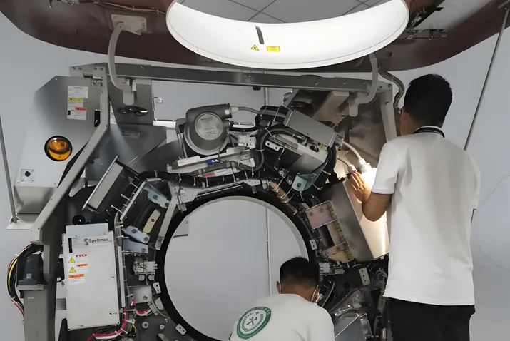
CT scanners are vital diagnostic tools in the medical field, relying heavily on intricate electronic systems. At the heart of these systems are PCBs that control everything from signal processing to power distribution. When a PCB fails, it can halt the entire machine, leading to costly downtime and delayed patient care. Learning PCB repair techniques specific to CT scanners ensures that technicians can quickly diagnose and fix issues, minimizing disruptions.
In this blog, we’ll walk you through the essentials of repairing these boards, from identifying faults to using rework stations for component replacement. Our goal is to equip you with actionable knowledge so you can tackle repairs with confidence.
Understanding the Basics of CT Scanner PCBs
Before diving into repair techniques, it’s important to understand the unique nature of PCBs in CT scanners. These boards often handle high-voltage signals, process data at speeds exceeding 1 GHz for real-time imaging, and manage multiple layers of circuitry. They’re designed with tight impedance control, often targeting values like 50 ohms for signal integrity. A single fault in a trace or component can distort image data or cause system failures.
Common issues include burnt components due to power surges, broken traces from mechanical stress, and failed capacitors or resistors due to prolonged heat exposure. Recognizing these problems is the first step in effective troubleshooting.
Essential Tools for PCB Repair
To perform repairs on CT scanner PCBs, you’ll need a well-equipped toolkit. Here’s a breakdown of the must-have tools for soldering, desoldering, and component replacement:
- Rework Stations: A quality rework station with adjustable temperature control (ranging from 200°C to 450°C) is crucial for soldering and desoldering tasks. Hot air rework stations are particularly useful for surface-mount components.
- Soldering Iron: Use a fine-tip soldering iron with a power rating of 25-40 watts for precision work on small components.
- Desoldering Tools: Desoldering pumps or wick are essential for removing old solder without damaging pads or traces.
- Multimeter: A digital multimeter helps measure voltage, resistance, and continuity to diagnose faults. Look for one with a resolution of at least 0.1 mV for accuracy.
- Magnifying Glass or Microscope: Many CT scanner PCBs have tiny components and traces, requiring magnification for detailed inspection.
- ESD Protection: Use an anti-static wrist strap and mat to prevent electrostatic discharge, which can damage sensitive components.
Step-by-Step Guide to CT Scanner PCB Repair
Repairing a PCB from a CT scanner requires a systematic approach. Below, we outline the key steps to guide you through the process, from troubleshooting to final testing.
Step 1: Initial Inspection and Safety Precautions
Start by powering down the CT scanner and disconnecting it from any power source. Wear appropriate safety gear, including gloves and ESD protection, to avoid injury or damage to the board. Visually inspect the PCB for obvious signs of damage, such as burnt components, bulging capacitors, or cracked traces. Use a magnifying tool to check for hairline fractures or corrosion, especially around high-voltage areas.
Step 2: Troubleshooting with a Flowchart
Troubleshooting is a critical skill in PCB repair. Using troubleshooting flowcharts can streamline the process by providing a logical path to identify faults. Here’s a basic flowchart to follow:
- Power Issues: Check if the board receives power. Use a multimeter to measure input voltage (typically 24V or 48V for CT scanner boards). If absent, trace back to the power supply unit.
- Signal Failures: If power is present but the scanner doesn’t function, test signal paths. Measure impedance across critical traces (should be around 50 ohms for high-speed lines). Deviations may indicate a broken trace or failed component.
- Component Testing: Test individual components like resistors, capacitors, and ICs for continuity or shorts. Replace any that show readings outside their specified range (e.g., a 10uF capacitor reading below 8uF likely needs replacement).
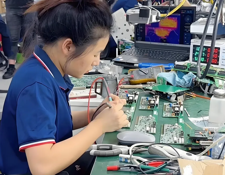
- Thermal Imaging: Use a thermal camera to detect overheating areas, which could point to short circuits or failing components drawing excessive current.
Step 3: Soldering and Desoldering Techniques
Once you’ve identified the faulty component, it’s time to remove and replace it. Soldering and desoldering are delicate tasks, especially on multi-layer PCBs found in CT scanners. Follow these tips:
- Desoldering: Use a desoldering pump or wick to remove old solder. Heat the joint with a soldering iron set to 300°C, then quickly apply the pump to suck up molten solder. Avoid excessive heat to prevent lifting pads or damaging nearby components.
- Soldering: Clean the area with isopropyl alcohol and apply fresh solder flux. Use lead-free solder with a melting point of around 217°C for compatibility with modern PCBs. Place the new component, heat the pad, and apply solder to create a shiny, conical joint.
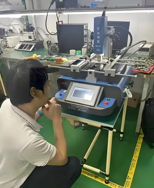
- Rework Station for SMDs: For surface-mount devices (SMDs), use a hot air rework station. Set the temperature to 350°C and airflow to a medium level to avoid blowing away adjacent components. Heat the area for 10-15 seconds, remove the old component with tweezers, and install the new one.
Step 4: Component Replacement
Component replacement requires precision to ensure compatibility and functionality. Always source replacement parts that match the original specifications, such as voltage ratings, capacitance, or resistance values. For example, if replacing a capacitor rated at 100uF 50V, using a lower voltage rating could lead to failure under load. Double-check pin configurations for ICs to avoid incorrect orientation, which can cause short circuits.
After replacement, inspect the solder joints under magnification to confirm there are no cold joints or bridges. A good joint should look smooth and shiny, not dull or cracked.
Step 5: Testing and Validation
Once repairs are complete, reassemble the PCB into the CT scanner and power it on in a controlled environment. Monitor for error codes or abnormal behavior. Use diagnostic software, if available, to run system checks and verify signal integrity. Measure key points with a multimeter to ensure voltages and currents are within expected ranges (e.g., a 5V line should not drop below 4.75V under load).
If the system still malfunctions, revisit the troubleshooting flowchart to identify any overlooked issues. Persistence and attention to detail are key in PCB repair.
Advanced PCB Repair Techniques for CT Scanners
For complex issues, technicians may need to employ advanced techniques. Here are a few methods to consider:
- Trace Repair: If a trace is broken, use a conductive pen or thin wire to bridge the gap. Ensure the repair can handle the current load (e.g., a trace carrying 2A requires a wire of at least 28 AWG).
- BGA Rework: Ball Grid Array (BGA) components are common in high-density CT scanner PCBs. Reworking them requires specialized equipment with precise temperature profiles (often peaking at 240°C for lead-free solder) to avoid damaging the board or chip.
- Firmware Checks: Sometimes, PCB issues are tied to firmware corruption. Connect the board to a compatible programmer and verify or reload the firmware to rule out software-related faults.
Preventing Future PCB Failures
While repairs are essential, preventing future issues saves time and resources. Here are some best practices:
- Regularly clean PCBs to remove dust and debris that can cause shorts or overheating.
- Monitor the operating environment of the CT scanner, keeping temperatures below 40°C and humidity under 60% to reduce stress on components.
- Schedule routine maintenance to check for early signs of wear, such as capacitor leakage or trace corrosion.
Challenges in CT Scanner PCB Repair
Repairing PCBs from CT scanners isn’t without challenges. The high density of components, multi-layer designs, and proprietary systems can make diagnosis and repair difficult. Additionally, accessing schematics or replacement parts for older models may require extra effort. Technicians must stay patient, use every available resource, and sometimes consult with peers or online communities for insights on specific issues.
Conclusion
Mastering CT scanner PCB repair is a valuable skill for technicians in the medical equipment field. By following this step-by-step guide, you can confidently tackle troubleshooting, soldering, desoldering, and component replacement using rework stations and other essential tools. With the help of troubleshooting flowcharts and a methodical approach, you’ll be able to diagnose and fix issues efficiently, ensuring minimal downtime for critical diagnostic equipment.
At ALLPCB, we’re committed to supporting technicians and engineers with resources and expertise in PCB-related challenges. Keep refining your PCB repair techniques, and you’ll become an indispensable asset in maintaining the functionality of life-saving medical technology.


