 ALLPCB


In the demanding world of oil rig operations, reliable technology is critical. One of the biggest challenges is designing printed circuit boards (PCBs) that can withstand the harsh environments of offshore drilling. This blog post dives into a real-world case study of a successful oil rig monitoring PCB design, tailored for extreme conditions. If you're searching for insights on oil rig PCB case studies, harsh environment PCB solutions, or successful PCB projects, you're in the right place. We'll explore the design process, challenges, solutions, and best practices to help engineers create durable and effective PCB designs.
Introduction to Oil Rig Monitoring and PCB Challenges
Oil rigs operate in some of the toughest environments on Earth. From extreme temperatures to high humidity, corrosive saltwater, and constant vibrations, the conditions are brutal for any electronic system. PCBs used in oil rig monitoring systems must endure these challenges while maintaining accuracy and reliability. These systems often track critical data like pressure, temperature, and equipment status, ensuring safety and efficiency.
Designing a PCB for such a setting is no easy task. Engineers face issues like thermal stress, moisture ingress, and mechanical shocks. In this case study, we'll walk through a successful project that tackled these problems head-on, providing a blueprint for harsh environment PCB design. Whether you're looking for PCB design examples or practical PCB best practices, this story offers valuable lessons.
The Project: Oil Rig Monitoring System Overview
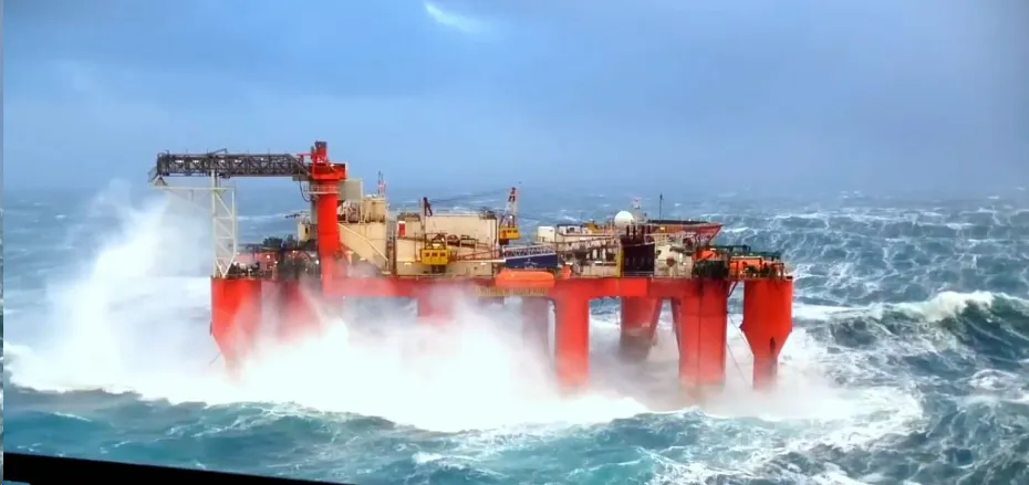
The project focused on creating a PCB for a monitoring system installed on an offshore oil rig in the North Sea. The system needed to collect real-time data from sensors monitoring pipeline pressure and temperature, with the PCB acting as the central processing unit. The goal was to ensure continuous operation for at least five years without failure, despite exposure to temperatures ranging from -40°C to 85°C, humidity levels up to 95%, and constant mechanical vibrations.
The PCB had to meet strict requirements: low power consumption (under 500 mW), high signal integrity for data transmission, and resistance to corrosion. This project serves as one of the standout successful PCB projects in the industry, demonstrating how careful planning and innovative design can overcome extreme challenges.
Key Challenges in Harsh Environment PCB Design
Before diving into the solutions, let’s outline the primary obstacles faced during this oil rig PCB case study. These challenges are common in harsh environment PCB projects and understanding them is the first step to overcoming them.
1. Extreme Temperature Variations
Temperature swings can cause thermal expansion and contraction in PCB materials, leading to cracks or delamination. For this project, the board needed to function reliably between -40°C and 85°C, a range that tests the limits of most standard materials.
2. Corrosion from Saltwater Exposure
Offshore rigs are surrounded by saltwater, which can corrode metal components and degrade PCB performance. Without proper protection, traces and connectors could fail within months.
3. Mechanical Stress and Vibrations
Constant vibrations from drilling equipment and rough seas can loosen components or crack solder joints. The PCB needed to withstand a vibration frequency of up to 50 Hz with an amplitude of 0.5 mm.
4. High Humidity and Moisture
Humidity levels near 95% can lead to condensation on the PCB, risking short circuits or component failure. Moisture ingress was a significant concern for long-term reliability.
Design Solutions for Harsh Environment PCB Success
With the challenges identified, the design team implemented several innovative solutions. These strategies align with PCB best practices and can be applied to other harsh environment PCB projects.
1. Material Selection for Durability
Standard FR-4 material was insufficient for this project due to its limited thermal and mechanical properties. Instead, the team chose a high-Tg (glass transition temperature) polyimide material with a Tg of 250°C. This material offers excellent thermal stability and resistance to moisture absorption (less than 0.8% by weight), making it ideal for extreme conditions.
For the solder mask, a high-performance epoxy-based coating was applied, providing additional protection against corrosion. Copper traces were plated with a 2-micron layer of immersion gold to prevent oxidation in the salty environment.
2. Robust Component Selection
Components were chosen based on their ability to operate in extended temperature ranges. For example, the microcontroller used had a specified operating range of -40°C to 105°C, exceeding the project’s requirements. Capacitors and resistors were selected with low thermal drift to maintain signal accuracy, ensuring impedance values stayed within ±5% of nominal values across the temperature range.
3. Conformal Coating for Moisture Protection
To combat high humidity, a silicone-based conformal coating was applied to the assembled PCB. This coating provided a barrier against moisture and dust, with a dielectric strength of 50 kV/mm to prevent electrical breakdown. The coating was tested to withstand 1000 hours of salt spray exposure without degradation.
4. Mechanical Design for Vibration Resistance
To handle vibrations, the PCB layout minimized the use of through-hole components, which are more prone to loosening. Surface-mount components were secured with high-strength adhesives, and the board was mounted using shock-absorbing dampers to reduce mechanical stress. The design passed a vibration test at 50 Hz for 72 hours without any failures.
5. Thermal Management Techniques
Thermal vias were strategically placed under high-power components to dissipate heat to a copper ground plane, keeping junction temperatures below 100°C even at the maximum ambient temperature of 85°C. Additionally, the layout avoided placing heat-sensitive components near power sources, maintaining signal integrity for data transmission at speeds up to 10 Mbps.
Testing and Validation: Ensuring Reliability
After the design phase, rigorous testing was conducted to validate the PCB’s performance under simulated oil rig conditions. These tests are critical in successful PCB projects and provide a model for other harsh environment designs.
1. Environmental Stress Testing
The PCB was subjected to thermal cycling between -40°C and 85°C for 500 cycles, with each cycle lasting 30 minutes. No delamination or trace cracks were observed, confirming the material’s durability.
2. Salt Spray Testing
A 1000-hour salt spray test was performed to simulate long-term exposure to a marine environment. The conformal coating and gold plating protected the board, showing no signs of corrosion or electrical failure.
3. Vibration and Shock Testing
The board underwent vibration testing at 50 Hz with a 0.5 mm amplitude for 72 hours, followed by shock testing with a peak acceleration of 30 g. All components remained intact, and signal integrity was maintained with no measurable noise increase.
4. Functional Testing
The monitoring system was tested for continuous operation over 30 days in a chamber simulating 95% humidity and 85°C. Data transmission accuracy remained above 99.9%, with no interruptions or failures.
Results and Impact of the Project
The final PCB design exceeded expectations, achieving a mean time between failures (MTBF) of over 100,000 hours, equivalent to more than 11 years of continuous operation. The oil rig monitoring system was deployed successfully, providing reliable data that improved operational safety and reduced downtime by 15% in the first year. Maintenance costs dropped significantly, as the durable design eliminated the need for frequent board replacements.
This project stands as a prime example of successful PCB projects, showcasing how tailored design solutions can conquer the challenges of harsh environments. It also highlights the importance of thorough testing and material selection in achieving long-term reliability.
PCB Best Practices for Harsh Environments
Based on this oil rig PCB case study, here are some actionable PCB best practices for engineers working on similar projects:
- Choose High-Performance Materials: Opt for substrates like polyimide with high Tg values and low moisture absorption for thermal and environmental stability.
- Protect Against Corrosion: Use immersion gold plating for traces and apply conformal coatings to shield against moisture and salt exposure.
- Design for Mechanical Stability: Minimize through-hole components, use adhesives for surface-mount parts, and incorporate shock-absorbing mounts.
- Focus on Thermal Management: Integrate thermal vias and heat sinks to manage temperature, ensuring components stay within safe operating limits.
- Test Rigorously: Simulate real-world conditions through thermal cycling, salt spray, and vibration tests to validate design durability before deployment.
Conclusion: Lessons from a Successful PCB Project
Designing a PCB for oil rig monitoring in harsh environments is a complex but achievable task. This case study demonstrates that with the right materials, thoughtful design, and thorough testing, engineers can create boards that thrive under extreme conditions. The success of this project offers valuable PCB design examples for anyone tackling similar challenges, whether in offshore drilling, aerospace, or other demanding industries.
By following the PCB best practices outlined here, you can enhance the reliability and lifespan of your designs, ensuring they perform flawlessly no matter the environment. Harsh environment PCB projects require attention to detail and a commitment to quality, but the results—safer operations, reduced costs, and improved performance—are well worth the effort.
If you're inspired by this oil rig PCB case study, consider applying these lessons to your next project. With the right approach, your design could be the next standout success story in the world of harsh environment electronics.


