 ALLPCB


In the fast-evolving world of military technology, precision and speed are everything. Advanced PCB (Printed Circuit Board) technology plays a critical role in high-speed missile guidance systems, ensuring accurate signal transmission and reliable performance under extreme conditions. If you're searching for insights on high-frequency PCB technology for missiles, high-speed PCB manufacturing guidance, precision signal transmission PCBs, or ultra-precise PCBs for guidance, you're in the right place. This blog dives deep into how cutting-edge PCB solutions empower missile guidance systems with unmatched accuracy and speed.
At ALLPCB, we understand the unique demands of such high-stakes applications. In this comprehensive guide, we'll explore the importance of advanced PCB technology, the specific requirements for missile guidance systems, and the manufacturing processes that ensure top-tier performance. Let's break down the key aspects of this technology to help you grasp its significance and potential.
Why Advanced PCB Technology Matters for Missile Guidance
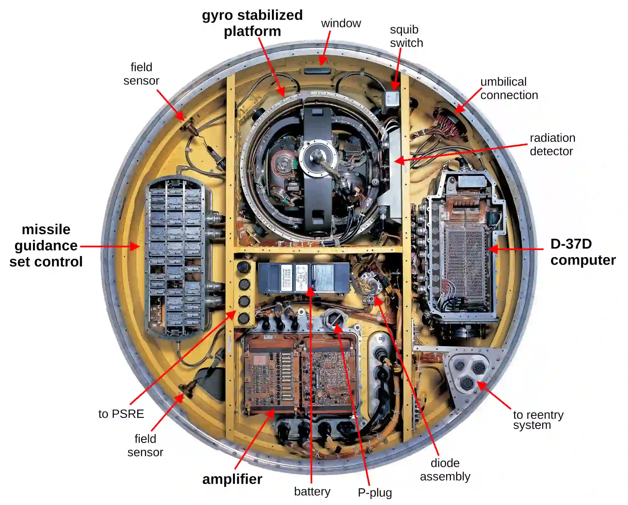
Missile guidance systems rely on real-time data processing and signal transmission to hit targets with pinpoint accuracy. Whether it's a short-range tactical missile or a long-range ballistic missile, the electronics inside must perform flawlessly under high stress, extreme temperatures, and intense vibrations. This is where advanced PCB technology comes into play.
PCBs in missile guidance systems handle high-frequency signals, often above 1 GHz, to communicate with sensors, control units, and navigation systems. A slight delay or signal loss can result in catastrophic failure. Therefore, using high-frequency PCB technology for missiles is not just an option—it's a necessity. These boards are designed to minimize signal interference, reduce latency, and maintain integrity even in harsh environments.
Key Features of High-Frequency PCB Technology for Missiles
High-frequency PCB technology for missiles is built to meet stringent requirements. Let's look at the critical features that make these boards suitable for such demanding applications:
- Low Dielectric Constant (Dk): A lower Dk value, typically below 3.5, reduces signal delay and enhances transmission speed. This is vital for real-time data processing in missile systems.
- Low Dissipation Factor (Df): A Df value below 0.005 minimizes signal loss, ensuring that data remains clear and accurate over long distances.
- High Thermal Stability: Missiles experience extreme heat during flight. PCBs must withstand temperatures ranging from -55°C to 125°C without degrading.
- Minimal Signal Interference: Advanced shielding and layout designs prevent electromagnetic interference (EMI), which could disrupt guidance signals.
- Compact and Lightweight Design: Space is limited in a missile. PCBs must be small yet powerful, often using multi-layer designs to pack more functionality into less space.
These features ensure that high-frequency PCBs can handle the rapid data exchange needed for missile navigation and targeting. Without them, achieving precision in high-speed scenarios would be nearly impossible.
High-Speed PCB Manufacturing Guidance for Missile Systems
Manufacturing PCBs for missile guidance systems is a highly specialized process. High-speed PCB manufacturing guidance focuses on precision, reliability, and adherence to strict standards. Here's how the process works and what sets it apart:
Material Selection
The choice of materials is critical for high-speed PCBs. Commonly used substrates include high-frequency laminates with excellent thermal and electrical properties. These materials ensure low signal loss and high durability. For missile applications, the materials must also resist moisture, chemicals, and mechanical stress.
Precision in Design and Layout
Designing a PCB for missile guidance requires ultra-precise layouts. Engineers use advanced software to simulate signal paths and identify potential issues like crosstalk or impedance mismatches. Controlled impedance, often maintained within ±10% tolerance (e.g., 50 ohms for RF signals), is crucial for consistent performance.
Advanced Fabrication Techniques
High-speed PCB manufacturing involves techniques like microvia drilling and fine-line etching to create intricate circuits. For missile systems, boards often feature line widths and spacing as small as 3 mils (0.003 inches). This precision allows for higher component density and faster signal transmission.
Testing and Validation
Every PCB undergoes rigorous testing to ensure it meets military-grade standards. Tests include thermal cycling, vibration testing, and signal integrity analysis. For instance, signal integrity tests might measure rise times as low as 100 picoseconds to confirm that the board can handle high-speed data without distortion.
Precision Signal Transmission PCB: The Backbone of Guidance Accuracy
A precision signal transmission PCB is at the heart of any missile guidance system. These boards ensure that signals from sensors, GPS, and control units are transmitted without loss or delay. Here's why precision in signal transmission matters and how it's achieved:
In missile systems, signals often travel at speeds exceeding 10 Gbps. Any interference or delay can throw off the missile's trajectory. Precision signal transmission PCBs are designed with specific features to avoid this:
- Matched Impedance: Ensures that signals travel without reflection or loss. A typical target impedance for high-speed lines is 50 ohms, with tight tolerances.
- Short Signal Paths: Reduces latency by minimizing the distance signals need to travel on the board.
- Advanced Layer Stacking: Multi-layer PCBs separate power, ground, and signal layers to reduce noise and improve clarity.
- High-Quality Connectors: Connectors with low insertion loss (below 0.5 dB) maintain signal strength during transmission.
By focusing on these elements, precision signal transmission PCBs enable missile guidance systems to process data in real-time, ensuring accurate targeting even at supersonic speeds.
Ultra-Precise PCB for Guidance: Meeting the Highest Standards
An ultra-precise PCB for guidance is the ultimate solution for missile systems requiring the highest level of accuracy. These boards are engineered to operate in the most challenging conditions while maintaining flawless performance. Let's explore what makes them unique:
Tight Tolerances in Manufacturing
Ultra-precise PCBs are manufactured with tolerances as tight as ±0.1 mil for trace widths and spacing. This level of accuracy ensures that every signal path is optimized for performance, leaving no room for error.
High Reliability Under Stress
Missile systems face intense mechanical stress during launch and flight. Ultra-precise PCBs are built to withstand vibrations up to 20g and shocks up to 100g, ensuring they remain operational no matter the conditions.
Integration with Advanced Technologies
These PCBs often integrate with cutting-edge technologies like inertial navigation systems (INS) and radar. They must support high-frequency signals (up to 40 GHz in some cases) and handle complex data from multiple sources simultaneously.
Challenges in Developing PCBs for Missile Guidance
While advanced PCB technology offers incredible benefits, developing these boards for missile guidance comes with unique challenges. Understanding these hurdles can help engineers and manufacturers create better solutions.
- Harsh Environmental Conditions: PCBs must operate reliably in extreme heat, cold, and humidity. Materials and designs need to account for thermal expansion, which can shift traces by up to 10 micrometers per degree Celsius.
- Miniaturization: Fitting powerful electronics into a small space requires innovative designs, like high-density interconnect (HDI) boards with microvias as small as 0.004 inches in diameter.
- Cost vs. Performance: Balancing the need for high performance with budget constraints is always a challenge. Advanced materials and manufacturing processes can drive up costs significantly.
- Regulatory Compliance: Military applications often require adherence to strict standards, such as MIL-PRF-31032, which governs PCB performance and reliability.
Overcoming these challenges requires collaboration between designers, manufacturers, and end-users to ensure that every board meets the necessary specifications.
How ALLPCB Supports Advanced PCB Solutions for Missile Guidance
At ALLPCB, we specialize in providing high-quality PCB solutions tailored to the needs of high-speed and high-frequency applications like missile guidance systems. Our expertise in precision manufacturing and advanced materials allows us to deliver boards that meet the strictest standards.
We offer comprehensive services, from design consultation to final production, ensuring that every PCB is optimized for performance. Our state-of-the-art facilities use the latest fabrication techniques to achieve tight tolerances and impeccable signal integrity. Whether you need a high-frequency PCB for missile systems or an ultra-precise PCB for guidance, we have the tools and experience to bring your project to life.
Future Trends in PCB Technology for Missile Guidance
The field of PCB technology is constantly evolving, and several trends are shaping the future of missile guidance systems. Staying ahead of these developments can give engineers and manufacturers a competitive edge.
- Higher Frequency Support: As missile systems adopt more advanced radar and communication technologies, PCBs will need to support frequencies above 60 GHz.
- Integration of AI: Artificial intelligence is being integrated into guidance systems for better decision-making. PCBs will need to handle increased data processing demands.
- Improved Materials: New dielectric materials with even lower Dk and Df values are being developed to further reduce signal loss and delay.
- 3D Printing: Additive manufacturing techniques are emerging as a way to create complex PCB structures with greater precision and less waste.
These trends highlight the importance of innovation in PCB design and manufacturing, ensuring that missile guidance systems remain at the forefront of military technology.
Conclusion
Advanced PCB technology is the foundation of high-speed missile guidance systems. From high-frequency PCB technology for missiles to ultra-precise PCBs for guidance, these components ensure that signals are transmitted with precision and reliability. By focusing on key features like low signal loss, thermal stability, and compact design, manufacturers can create boards that meet the extreme demands of military applications.
At ALLPCB, we're committed to pushing the boundaries of what's possible in PCB manufacturing. Whether you're working on a missile guidance project or another high-stakes application, our team is ready to provide the expertise and solutions you need. With the right PCB technology, achieving precision and speed in missile systems is not just a goal—it's a reality.


