 ALLPCB


Are you an electrical engineer looking to harness the power of thyristors in your PCB designs? Thyristors, often known as Silicon Controlled Rectifiers (SCRs), are vital components in power electronics, offering unique switching capabilities for various applications. In this guide, we’ll dive deep into thyristor applications in PCB design, explore thyristor circuit examples, discuss thyristor selection for PCBs, and provide practical tips on PCB thyristor mounting and thyristor PCB layout guidelines. Whether you’re designing circuits for motor control or power regulation, this blog will equip you with the knowledge to integrate thyristors effectively.
Let’s unlock the potential of thyristors in PCB design with a detailed look at their functions, practical uses, and best practices for implementation.
What Are Thyristors and Why Use Them in PCB Design?
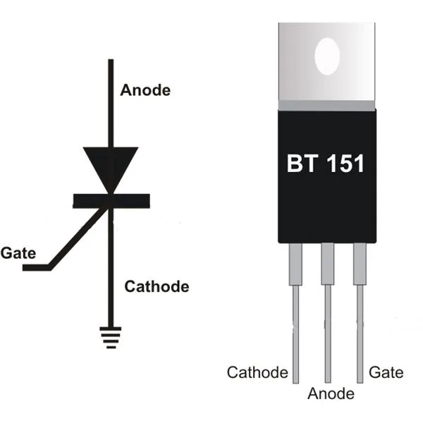
Thyristors are semiconductor devices with three electrodes—anode, cathode, and gate—that act as switches in high-power applications. Unlike transistors, which can operate in a range of states, thyristors are binary: they’re either fully on or fully off. This makes them perfect for applications where you need to control large currents or voltages with minimal power loss.
In PCB design, thyristors are often used for their ability to handle high voltages (up to 1000V or more) and currents (often exceeding 100A in industrial applications). They’re especially valuable in circuits requiring phase control, overcurrent protection, or switching operations. By incorporating thyristors, you can enhance the reliability and efficiency of power management systems on your PCB.
Key Thyristor Applications in PCB Design
Thyristors play a critical role in several PCB applications, especially in power electronics. Here are some of the most common uses for electrical engineers to consider:
1. Power Control and Regulation
Thyristors are widely used in AC power control circuits, such as dimmer switches and motor speed controllers. They allow precise control over power delivery by adjusting the phase angle at which they turn on during each AC cycle. For instance, in a light dimmer circuit, a thyristor can control the RMS voltage applied to the load, typically ranging from 0V to 120V or 240V, depending on the system.
2. Overcurrent and Overvoltage Protection
In PCB designs for industrial equipment, thyristors can act as crowbar protection devices. When a fault condition like an overvoltage (e.g., exceeding 300V in a 240V system) is detected, the thyristor turns on to short-circuit the power supply and protect sensitive components. This is critical in preventing damage to microcontrollers or other ICs on the board.
3. Switching in DC and AC Circuits
Thyristors, especially Gate Turn-Off (GTO) types, are used as high-power switches in DC and AC circuits. They can handle currents up to 500A in some configurations, making them ideal for applications like inverters and rectifiers integrated into PCBs for renewable energy systems.
Thyristor Circuit Examples for PCB Integration
Let’s explore some practical thyristor circuit examples that you can implement in your PCB designs. These examples will help you understand how thyristors function in real-world applications.
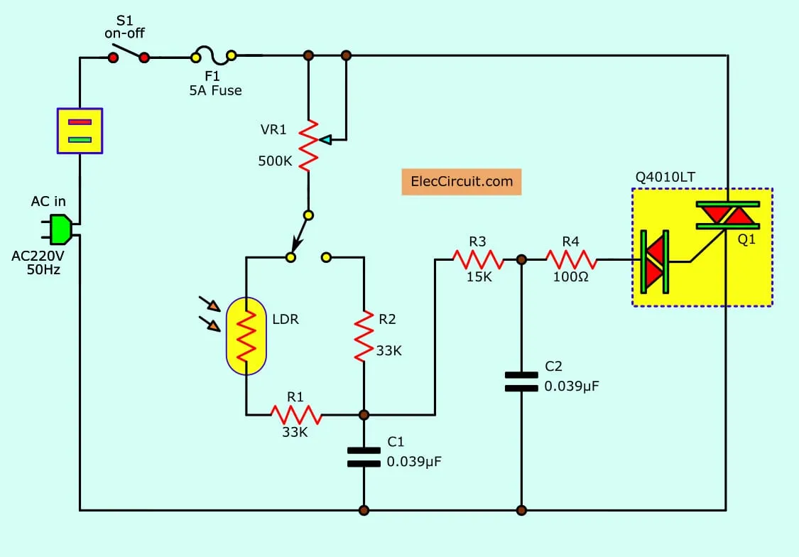
Example 1: AC Power Control Circuit
A classic use of thyristors is in AC power control. Consider a circuit with a TRIAC (a bidirectional thyristor) for controlling a 240V AC load, such as a heater. The TRIAC is triggered by a gate pulse generated by a microcontroller through an opto-isolator (like the MOC3021). The triggering angle determines the power delivered to the load, with a delay of 0 to 8.3ms (for a 60Hz system) corresponding to full off to full on.
On the PCB, ensure the TRIAC is placed near heavy copper traces to handle currents up to 10A, and include a heat sink if power dissipation exceeds 5W.
Example 2: Crowbar Protection Circuit
In a crowbar circuit, an SCR is connected across the power supply output. If the voltage exceeds a threshold (say, 15V for a 12V system), a Zener diode triggers the SCR’s gate, causing it to conduct and short the supply, thus protecting downstream components. For PCB layout, place the SCR close to the power input with wide traces to handle fault currents up to 50A momentarily.
Thyristor Selection for PCBs: What to Consider
Choosing the right thyristor for your PCB design is crucial for performance and reliability. Here are key factors to guide your thyristor selection for PCBs:
1. Voltage and Current Ratings
Select a thyristor with voltage and current ratings at least 20-30% higher than your circuit’s maximum operating conditions. For example, for a 240V AC system, choose a thyristor rated for at least 300V. Similarly, if your load draws 20A, opt for a device rated for 25A or more to account for surges.
2. Gate Triggering Requirements
Check the gate trigger current (IGT) and voltage (VGT) needed to turn on the thyristor. Typical values might be 20mA and 1.5V, respectively. Ensure your control circuit can provide these levels reliably, even under varying temperatures (-40°C to 85°C for industrial applications).
3. Type of Thyristor
Decide between an SCR (unidirectional), TRIAC (bidirectional), or GTO thyristor based on your application. SCRs are ideal for DC circuits, while TRIACs suit AC power control. GTOs offer turn-off capability but may require more complex gate drive circuits on the PCB.
4. Thermal Management
Thyristors generate heat, especially at high currents. Look at the junction-to-ambient thermal resistance (RθJA), often around 1.5°C/W for TO-220 packages. Ensure your PCB design includes adequate heat sinking or forced air cooling if power dissipation exceeds 10W.
PCB Thyristor Mounting: Best Practices for Reliability
Proper PCB thyristor mounting is essential to ensure electrical performance and PCB thermal management. Follow these tips to avoid common pitfalls:
1. Use Appropriate Packages
Thyristors come in packages like TO-220, TO-247, or surface-mount D2PAK. For high-power applications (above 10A), through-hole packages like TO-220 are preferred due to better heat dissipation when paired with a heat sink. Surface-mount options are suitable for lower power (below 5A) and space-constrained designs.
2. Secure Mounting with Heat Sinks
For through-hole thyristors, mount them to the PCB with screws or clips to ensure firm contact with a heat sink. Use thermal grease with a thermal conductivity of at least 1 W/m·K to improve heat transfer. Ensure the heat sink is grounded if the thyristor tab is electrically live (common in TO-220AB packages).
3. Minimize Mechanical Stress
Avoid excessive bending of leads during mounting, as this can damage the thyristor’s internal structure. For automated assembly, ensure pick-and-place machines are calibrated to handle thyristor packages without applying undue force.
Thyristor PCB Layout Guidelines for Optimal Performance
A well-thought-out PCB layout is critical for thyristor performance and circuit reliability. Here are actionable thyristor PCB layout guidelines for engineers:
1. Place Thyristors Near Power Paths
Position thyristors close to the power input or load to minimize trace length and reduce parasitic inductance. Long traces can introduce voltage drops or ringing, especially in high-current applications (above 10A). Use trace widths that support the current, such as 0.5mm per amp for 1oz copper.
2. Separate Gate Drive Signals
Keep gate drive traces away from high-current or high-voltage paths to prevent noise coupling. If possible, route gate signals on a different PCB layer. Add a small resistor (e.g., 10Ω) in series with the gate to limit current spikes and improve switching stability.
3. Ensure Adequate Clearance and Creepage
For high-voltage thyristors (above 300V), maintain clearance and creepage distances as per IPC-2221 standards—typically 0.6mm for every 100V on outer layers. This prevents arcing and ensures safety in humid or dusty environments.
4. Ground Planes and Thermal Vias
Use a solid ground plane under the thyristor to reduce EMI and improve thermal dissipation. Add thermal vias (e.g., 0.3mm diameter, spaced 1mm apart) under surface-mount thyristors to transfer heat to the opposite side of the PCB or to an internal copper layer.
Common Challenges and Solutions in Thyristor-Based PCB Designs
While thyristors are powerful components, they come with design challenges. Here are some common issues and how to address them:
1. False Triggering
Thyristors can turn on unexpectedly due to noise or dv/dt effects (rapid voltage changes). To prevent this, add a snubber circuit (e.g., a 0.1μF capacitor and 100Ω resistor in parallel with the thyristor) to dampen transients. Ensure gate traces are short and shielded.
2. Thermal Runaway
Excessive heat can cause thyristors to fail or trigger unpredictably. Monitor junction temperatures (keep below 125°C for most devices) and use heat sinks or fans if ambient temperatures exceed 40°C. Check the thyristor’s datasheet for derating curves above 25°C.
3. Commutation Issues in AC Circuits
In AC applications, thyristors may fail to turn off if the current doesn’t drop to zero. Use forced commutation circuits or select TRIACs designed for inductive loads if your circuit includes motors or transformers.
Conclusion: Empowering Your PCB Designs with Thyristors
Thyristors are indispensable for electrical engineers working on power electronics and PCB design. From controlling AC power to protecting circuits from faults, their applications are vast and impactful. By understanding thyristor applications in PCB design, leveraging thyristor circuit examples, making informed choices during thyristor selection for PCBs, and following best practices for PCB thyristor mounting and thyristor PCB layout guidelines, you can create robust and efficient designs.


