 ALLPCB


Designing flexible circuits is a game-changer in electronics, allowing engineers to create compact, lightweight, and adaptable devices. But to achieve this, you need the right tools. If you're searching for flexible PCB design software, solutions for flex PCB layout, or tools for rigid flex PCB design, you're in the right place. Additionally, understanding bend radius calculation software and material selection for flex PCB is crucial for success. In this comprehensive guide, we'll explore the best software options and key considerations to help you master flexible circuit design.
Why Flexible Circuits Are Revolutionizing Electronics
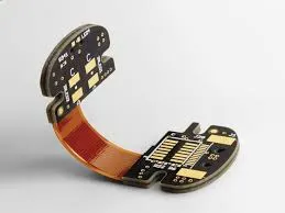
Flexible circuits, or flex PCBs, are transforming the electronics industry by enabling designs that rigid boards simply can't match. These circuits can bend, fold, and twist, making them ideal for wearables, medical devices, automotive systems, and more. Their lightweight nature and ability to fit into tight spaces reduce the overall size and weight of devices, often cutting assembly costs by up to 30% compared to traditional rigid designs.
However, designing flex PCBs comes with unique challenges like ensuring durability during bending, selecting the right materials, and calculating safe bend radii. This is where specialized PCB design software steps in, offering tools to tackle these issues head-on.
Key Features to Look for in Flexible PCB Design Software
When choosing software for flex PCB layout or rigid flex PCB design, certain features are non-negotiable. Here's what to prioritize:
1. Support for Flex and Rigid-Flex Designs
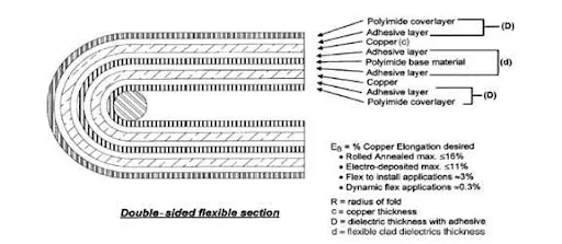
Not all PCB design tools handle flexible circuits. Look for software that explicitly supports flex and rigid-flex designs, allowing you to define flexible areas, rigid zones, and transition regions. This ensures accurate layer stack-ups and prevents design errors during manufacturing.
2. Bend Radius Calculation Tools
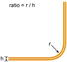
Bend radius is critical in flex PCB design. A bend that's too tight can crack traces or damage materials, leading to failure. Good bend radius calculation software integrates directly into the design environment, letting you simulate bending areas and set constraints. For instance, a common guideline is maintaining a bend radius of at least 6 times the thickness of the flex material—software can help enforce this rule automatically.
3. Material Library and Selection Support
Material selection for flex PCB impacts performance and durability. Software with built-in material libraries can guide you in choosing substrates like polyimide (PI) or polyester (PET), which offer flexibility and heat resistance. Some tools even suggest material thicknesses (e.g., 25-50 microns for thin flex layers) based on your design needs.
4. 3D Visualization and Simulation
Seeing how your flex PCB will behave in real-world conditions is invaluable. Software with 3D visualization lets you model bending, folding, and assembly, identifying potential stress points before production. This can save significant costs, as rework due to design flaws can increase project expenses by 20-40%.
5. Manufacturing Output and DFM Checks
Design for Manufacturability (DFM) checks tailored for flex PCBs ensure your design meets fabrication limits, such as minimum trace widths (typically 3-5 mils for flex) and spacing. Software should also generate precise outputs like Gerber files and stack-up documentation for seamless communication with manufacturers.
Top Software Options for Flexible PCB Design
While many tools exist for PCB design, only a few excel at handling flexible and rigid-flex circuits. Below, we discuss key categories and features of software that support flexible PCB design software needs without mentioning specific brand names, focusing instead on capabilities and benefits.
1. Professional-Grade Tools for Complex Designs
For engineers working on intricate rigid flex PCB design, professional tools offer advanced features like multi-zone layer management and dynamic bending simulations. These platforms often include automated routing for flex areas, ensuring signal integrity by maintaining consistent impedance (e.g., 50 ohms for high-speed signals). They also integrate with mechanical CAD systems to align PCB designs with enclosures, reducing errors in compact devices.
2. Open-Source Solutions for Budget-Friendly Design
If cost is a concern, open-source tools provide a viable option for flex PCB layout. While they may lack some advanced features, many support basic flex design through custom layer definitions and manual bend area setup. These tools are ideal for hobbyists or small projects, though they often require more manual effort to achieve precise results.
3. Cloud-Based Platforms for Collaboration
Modern cloud-based design environments are gaining traction for their ease of access and team collaboration features. Some support flex PCB design by offering shared libraries for materials and components, ensuring consistency across teams. These platforms are particularly useful for distributed teams working on wearable or IoT devices, where flex circuits are common.
Mastering Bend Radius Calculation for Flex PCBs
One of the biggest hurdles in flex PCB design is getting the bend radius right. A miscalculation can lead to cracked traces or delamination, causing circuit failure. Using bend radius calculation software simplifies this process, but understanding the basics is key.
Understanding Bend Radius Basics
The bend radius is the minimum radius a flex PCB can be bent without damage. For single-layer flex PCBs, a safe bend radius is often 6-10 times the material thickness. For multilayer designs, this increases to 10-12 times due to added stiffness. For example, a 0.1 mm thick single-layer flex PCB should have a minimum bend radius of 0.6-1.0 mm.
Software Tools for Bend Radius
Many design tools include built-in calculators to set bend radius constraints. These features allow you to define flexible zones and simulate bending stress, ensuring traces remain intact. Some even provide warnings if your design violates safe bending limits, helping avoid costly prototypes.
Tips for Safe Bending Design
- Place traces perpendicular to the bend line to minimize stress.
- Avoid vias or components in bending areas, as they can crack under strain.
- Use teardrop-shaped pads at trace ends to reduce stress concentration.
Material Selection for Flex PCB: Choosing Wisely
Material selection for flex PCB directly affects performance, cost, and manufacturability. Unlike rigid PCBs, flex circuits require substrates and adhesives that can withstand repeated bending without degrading.
Common Flex PCB Materials
- Polyimide (PI): The most popular choice due to its high thermal stability (up to 260°C) and flexibility. It's ideal for applications like aerospace and medical devices.
- Polyester (PET): A cost-effective option for less demanding applications, with lower thermal resistance (around 150°C).
- Adhesives: Acrylic or epoxy adhesives bond layers in multilayer flex designs, with thicknesses ranging from 12-25 microns.
Software Support for Material Selection
Advanced PCB design tools often include material databases that list properties like dielectric constant (typically 3.2-3.5 for PI) and tensile strength. These databases help you match materials to your design's electrical and mechanical needs, ensuring reliability.
Factors to Consider
- Thickness: Thinner materials (e.g., 25 microns) offer greater flexibility but less durability.
- Environment: Harsh conditions like high humidity or temperature swings may require PI over PET.
- Cost: PI can be 2-3 times more expensive than PET, impacting budget decisions.
Best Practices for Flex PCB Layout Design
Creating a successful flex PCB layout requires attention to detail beyond what rigid boards demand. Here are proven tips to ensure your design performs well and lasts long.
1. Optimize Trace Routing
Keep traces as straight as possible in flex areas to reduce stress. If curves are needed, use gradual arcs rather than sharp angles. Maintain consistent trace widths (e.g., 4-6 mils for signal lines) to avoid weak points.
2. Define Flex and Rigid Zones Clearly
In rigid flex PCB design, clearly mark transition zones between rigid and flex areas. Software tools often let you assign different stack-ups to these zones, ensuring accurate impedance control and layer alignment.
3. Minimize Component Stress
Place heavy or large components on rigid sections to avoid stress during bending. For flex areas, use lightweight, low-profile parts to maintain flexibility.
4. Test with Simulations
Before finalizing your design, run simulations to check for signal integrity and mechanical stress. Many software platforms offer tools to simulate bending cycles (e.g., 10,000 cycles for durability testing), helping predict long-term performance.
Challenges in Flexible PCB Design and How Software Helps
Designing flex PCBs isn't without hurdles. Common issues include signal loss due to bending, thermal expansion mismatches, and manufacturing errors. Here's how software addresses these challenges:
- Signal Integrity: Tools analyze impedance and crosstalk, adjusting trace spacing (e.g., 5-10 mils for high-speed lines) to maintain performance.
- Thermal Management: Simulations predict heat dissipation in flex materials, guiding material and thickness choices.
- Manufacturing Errors: DFM checks flag issues like overly tight bend radii or unsupported vias before production.
Conclusion: Bending the Future of Electronics with the Right Tools
Flexible circuits are reshaping electronics, enabling innovative designs in everything from smartphones to medical implants. But to unlock their potential, you need robust flexible PCB design software that supports flex PCB layout, rigid flex PCB design, and critical calculations like bend radius. By focusing on features like bend radius calculation software and prioritizing material selection for flex PCB, you can create reliable, high-performance designs.
Whether you're a seasoned engineer or just starting with flex circuits, the right software simplifies the process, reduces errors, and speeds up time-to-market. At ALLPCB, we're committed to supporting your journey with resources and expertise to bring your flexible designs to life. Start exploring the tools and tips shared here, and bend the rules of electronics in your favor.


