ALLPCB


As a PCB designer or electrical engineer, understanding triac datasheets is crucial for selecting the right component for your power control circuits. Triacs are widely used in AC power switching applications, but their datasheets can be dense with technical jargon and parameters. If you're wondering how to interpret key triac datasheet parameters like voltage rating, current rating, gate trigger current, or dv/dt rating, you've come to the right place. This guide will break down everything you need to know about triac datasheets, from basic specs to advanced considerations like snubber circuits, ensuring you can design reliable and efficient circuits.
In this comprehensive blog post, we'll dive deep into the critical aspects of triac datasheets, explaining each parameter with practical examples and actionable insights. Whether you're a seasoned engineer or just starting with triac-based designs, this guide will help you navigate the complexities of triac specifications and apply them to your projects. Let's get started!
Why Triac Datasheets Matter for PCB Designers
Triacs are semiconductor devices used to control AC power in applications like dimmers, motor speed controls, and heating systems. However, choosing the wrong triac or misinterpreting its specifications can lead to circuit failure, overheating, or even safety hazards. A triac datasheet is your roadmap to understanding the device's capabilities and limitations. It provides detailed information on electrical characteristics, thermal limits, and application guidelines—everything you need to integrate the triac into your PCB design successfully.
For PCB designers, decoding triac datasheet parameters ensures that the component matches the circuit's voltage, current, and environmental requirements. It also helps in designing protective circuits like snubber networks to prevent unwanted triggering. By mastering triac datasheets, you can avoid costly redesigns and ensure your circuits perform reliably under real-world conditions.
Recommended Reading: Triacs vs. Thyristors vs. Transistors: Choosing the Right Switch for Your PCB
Key Triac Datasheet Parameters Explained
Let's break down the most important triac datasheet parameters that every PCB designer should understand. We'll cover each specification with clear definitions, typical values, and their relevance to your design process.
1. Triac Voltage Rating (VDRM and VRRM)
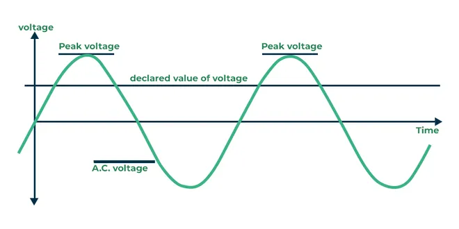
The voltage rating of a triac, often listed as VDRM (Repetitive Peak Off-State Voltage) and VRRM (Repetitive Peak Reverse Voltage), indicates the maximum voltage the triac can withstand when it is not conducting. For example, a triac with a VDRM of 600V can handle AC voltages up to 600V peak without breaking down. This parameter is critical when designing for mains-powered applications, such as in 120V or 240V systems.
Practical Tip: Always choose a triac with a voltage rating at least 20-30% higher than the peak voltage of your AC source to account for transients and spikes. For a 240V AC system (peak voltage of about 340V), a triac with a 600V rating provides a safe margin.
2. Triac Current Rating (IT(RMS))
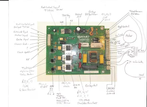
The current rating, denoted as IT(RMS), specifies the maximum RMS current the triac can carry continuously without overheating. For instance, a triac like the BT136 has a current rating of 4A, making it suitable for low-power applications like lamp dimmers. Higher-rated triacs, such as the BTA16 with a 16A rating, are better for heavy loads like motor controls.
Practical Tip: Consider the thermal environment of your PCB. If the triac is mounted in a confined space with poor ventilation, derate the current rating by 10-20% to prevent thermal runaway. Also, ensure proper heat sinking if the current approaches the rated maximum.
3. Triac Gate Trigger Current (IGT)
The gate trigger current (IGT) is the minimum current required at the gate terminal to turn the triac on. This value varies depending on the triac's quadrant of operation (I, II, or III) and is typically in the range of 5mA to 50mA for common triacs like the BT139. Understanding IGT is essential for designing the gate drive circuit, ensuring your control signal can reliably trigger the triac.
Practical Tip: Check the datasheet for IGT variations across temperature ranges, as this parameter often increases at lower temperatures. Design your gate driver to provide at least double the specified IGT to ensure reliable triggering.
4. Triac Holding Current (IH)
The holding current (IH) is the minimum current that must flow through the triac to keep it in the conducting state after it has been triggered. If the load current drops below IH, the triac will turn off. Typical values for IH range from 5mA to 75mA, depending on the device.
Practical Tip: For inductive loads like motors, ensure the load current remains above IH during operation, or the triac may unexpectedly turn off, causing erratic behavior. If necessary, add a resistive load in parallel to maintain the minimum current.
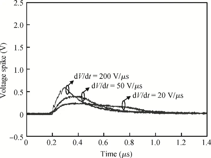
5. Triac dv/dt Rating
The dv/dt rating measures the triac's ability to withstand rapid changes in voltage across its terminals without falsely triggering. Expressed in volts per microsecond (V/μs), a higher dv/dt rating indicates better immunity to voltage transients. For example, a triac with a dv/dt rating of 500V/μs is less likely to turn on accidentally during voltage spikes compared to one with a 100V/μs rating.
Practical Tip: In noisy environments or with inductive loads, a low dv/dt rating can lead to unintended triggering. Use a snubber circuit (discussed later) to limit the rate of voltage change if the triac’s dv/dt rating is insufficient for your application.
6. Triac Operating Temperature Range
The operating temperature range, typically listed as Tj (junction temperature), defines the safe temperature limits for the triac, often between -40°C to 125°C for devices like the BTA16. Exceeding the maximum junction temperature can degrade performance or cause permanent damage.
Practical Tip: Account for ambient temperature and heat dissipation in your PCB layout. Place triacs away from other heat-generating components, and use thermal vias or heat sinks to keep Tj within limits. Check the datasheet for thermal resistance values (Rth(j-a)) to calculate heat dissipation needs.
Understanding Triac Package Types
Triacs come in various package types, each suited to different power levels and mounting requirements. Common packages include TO-220 (through-hole, often with a tab for heat sinking), D2PAK (surface-mount, high-power), and SOT-223 (surface-mount, low-power). The package type affects thermal management, current handling, and PCB layout.
For example, a TO-220 package like the one used in the BTA16-600 is ideal for high-power applications due to its ability to attach to a heat sink. In contrast, a SOT-223 package is better for compact, low-power designs but may require careful thermal design on the PCB.
Practical Tip: Review the datasheet for package-specific thermal resistance values and footprint dimensions. Ensure your PCB design accommodates the package's mounting and heat dissipation needs, especially for high-current triacs.
Interpreting Triac Graphs in Datasheets
Triac datasheets often include graphs that provide deeper insight into the device's behavior under various conditions. Understanding these graphs is essential for predicting performance and avoiding design pitfalls.
Common Graphs to Look For:
- On-State Voltage vs. Current: Shows the voltage drop across the triac when conducting. Use this to estimate power dissipation (e.g., a 1.5V drop at 10A results in 15W of heat).
- Gate Trigger Current vs. Temperature: Indicates how IGT changes with temperature. Use this to ensure reliable triggering across the operating range.
- Thermal Derating Curve: Shows how much current the triac can handle as temperature rises. Use this to derate the device in hot environments.
Practical Tip: When interpreting triac graphs, always cross-reference them with your application's operating conditions. For instance, if your circuit operates at 80°C, use the thermal derating curve to adjust the maximum allowable current.
Triac Application Notes: Practical Design Tips
Most triac datasheets include application notes or recommended circuits to guide designers. These notes often cover topics like gate drive design, load types (resistive vs. inductive), and protection mechanisms. For example, application notes for the BT139 suggest using a gate resistor of 100-220 ohms to limit gate current while ensuring reliable triggering.
Practical Tip: Follow the manufacturer's application notes for initial design, but test the circuit under real-world conditions. Inductive loads, for instance, often require additional protection beyond what's mentioned in the datasheet.
Designing Triac Snubber Circuits for Protection
One of the most critical aspects of triac design is managing voltage transients, especially with inductive loads. A snubber circuit, typically consisting of a resistor and capacitor in series, is connected across the triac to limit the rate of voltage change (dv/dt). Without a snubber, rapid voltage changes can cause the triac to trigger unintentionally or fail.
Typical Snubber Values: For a 240V AC application with a moderate inductive load, a snubber circuit with a 100-ohm resistor and a 0.1μF capacitor (rated for at least 400V) is often sufficient. However, consult the triac datasheet for specific recommendations, as some modern triacs (like "snubberless" types) have high dv/dt ratings and may not require external snubbers.
Practical Tip: Place the snubber circuit as close as possible to the triac terminals on the PCB to minimize parasitic inductance. Use high-voltage capacitors to avoid breakdown during transients.
Common Pitfalls When Working with Triac Datasheets
Even experienced designers can make mistakes when interpreting triac datasheets. Here are some common pitfalls to avoid:
- Ignoring Temperature Effects: Parameters like IGT and IH change with temperature. Always design for the worst-case scenario.
- Underestimating Transients: Voltage spikes in AC systems can exceed the triac's VDRM. Use overrated components or protective circuits.
- Poor Thermal Management: Failing to account for heat dissipation can lead to triac failure. Always calculate power dissipation and use appropriate cooling.
Conclusion: Mastering Triac Datasheets for Better PCB Designs
Decoding triac datasheets is a vital skill for PCB designers working on AC power control circuits. By understanding key parameters like triac voltage rating, current rating, gate trigger current, holding current, dv/dt rating, and operating temperature, you can select the right component for your application and avoid common design errors. Additionally, leveraging application notes, interpreting triac graphs, and designing effective snubber circuits will ensure your circuits are robust and reliable.
Take the time to study the datasheet for each triac you use, and don't hesitate to test your designs under real-world conditions. With the insights from this guide, you're well-equipped to tackle triac-based projects with confidence. Have a specific triac or application in mind? Drop a comment below, and let's discuss how to optimize your design and start your PCB prototype in ALLPCB!