 ALLPCB


If you're new to electronics and looking to master through-hole component identification, you're in the right place. This guide will teach you the essentials of identifying through-hole resistors, capacitors, component codes, polarity, and distinguishing between axial and radial lead components. Whether you're assembling a circuit board or troubleshooting a project, understanding these basics is key to success. Let's dive into a detailed handbook that breaks down everything you need to know in a simple, step-by-step manner.
What Are Through-Hole Components?
Through-hole components are electronic parts with leads (metal wires) that are inserted into holes drilled on a printed circuit board (PCB) and soldered to create a strong connection. Unlike surface-mount components, which are smaller and soldered directly onto the board's surface, through-hole components are larger and easier to handle, making them ideal for beginners. They are commonly used in educational kits, prototyping, and applications where durability is important.
In this guide, we'll focus on identifying these components, understanding their markings, and learning how to place them correctly on a board. By the end, you'll be confident in handling through-hole resistor identification, recognizing through-hole capacitor types, and more.

Why Through-Hole Component Identification Matters
Correctly identifying through-hole components is crucial for building functional circuits. Using the wrong component or installing it incorrectly can lead to circuit failure, short circuits, or even damage to other parts. For beginners, learning to read markings, understand polarity, and recognize lead types saves time and prevents costly mistakes. Let's break down the key areas of focus for through-hole component identification.
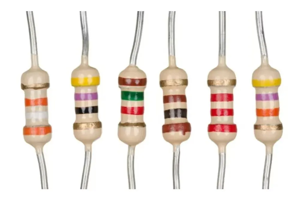
Through-Hole Resistor Identification: Decoding Color Bands
Resistors are one of the most common through-hole components, used to limit current or divide voltage in a circuit. Identifying a through-hole resistor involves reading its color bands, which indicate its resistance value and tolerance.
Most through-hole resistors have four or five color bands. Here's how to read them:
- First Band: Represents the first digit of the resistance value.
- Second Band: Represents the second digit.
- Third Band: Acts as a multiplier (in a four-band resistor) or the third digit (in a five-band resistor).
- Fourth Band: Indicates the tolerance, or how precise the resistance value is (e.g., ±5% or ±10%).
- Fifth Band (if present): Shows temperature coefficient or an additional tolerance factor.
For example, a resistor with bands Brown, Black, Red, and Gold translates to a value of 1,000 ohms (1 kΩ) with a tolerance of ±5%. You can use online color code calculators or charts to practice decoding these values.
Resistors typically come in axial form, meaning their leads extend from both ends of a cylindrical body. When placing them on a PCB, orientation doesn't matter since resistors are non-polarized.
Through-Hole Capacitor Types: Understanding Varieties and Markings
Capacitors store and release electrical energy in a circuit, and through-hole capacitors come in various types, each with distinct purposes and markings. Let's explore the main through-hole capacitor types and how to identify them.
1. Ceramic Capacitors
These are small, often disc-shaped capacitors used for high-frequency applications. They are non-polarized, meaning they can be installed in any direction. Their value is usually marked in picofarads (pF) with a three-digit code. For instance, a marking of "104" means 10 followed by 4 zeros, or 100,000 pF, which equals 0.1 μF.
2. Electrolytic Capacitors
These are larger, cylindrical capacitors used for filtering and power supply applications. They are polarized, so correct orientation is critical. The negative lead is often marked with a stripe or a minus sign, while the positive lead may be longer. Their value (in microfarads, μF) and voltage rating are printed directly on the body, such as "100μF 16V."
3. Film Capacitors
These are used for noise suppression and timing circuits. They are often rectangular or cylindrical and non-polarized. Their markings may show values directly, like "0.047 μF," or use a code similar to ceramic capacitors.
Understanding through-hole capacitor types helps in selecting the right one for your circuit and installing it correctly to avoid damage.
Reading Through-Hole Component Codes: Beyond Resistors and Capacitors
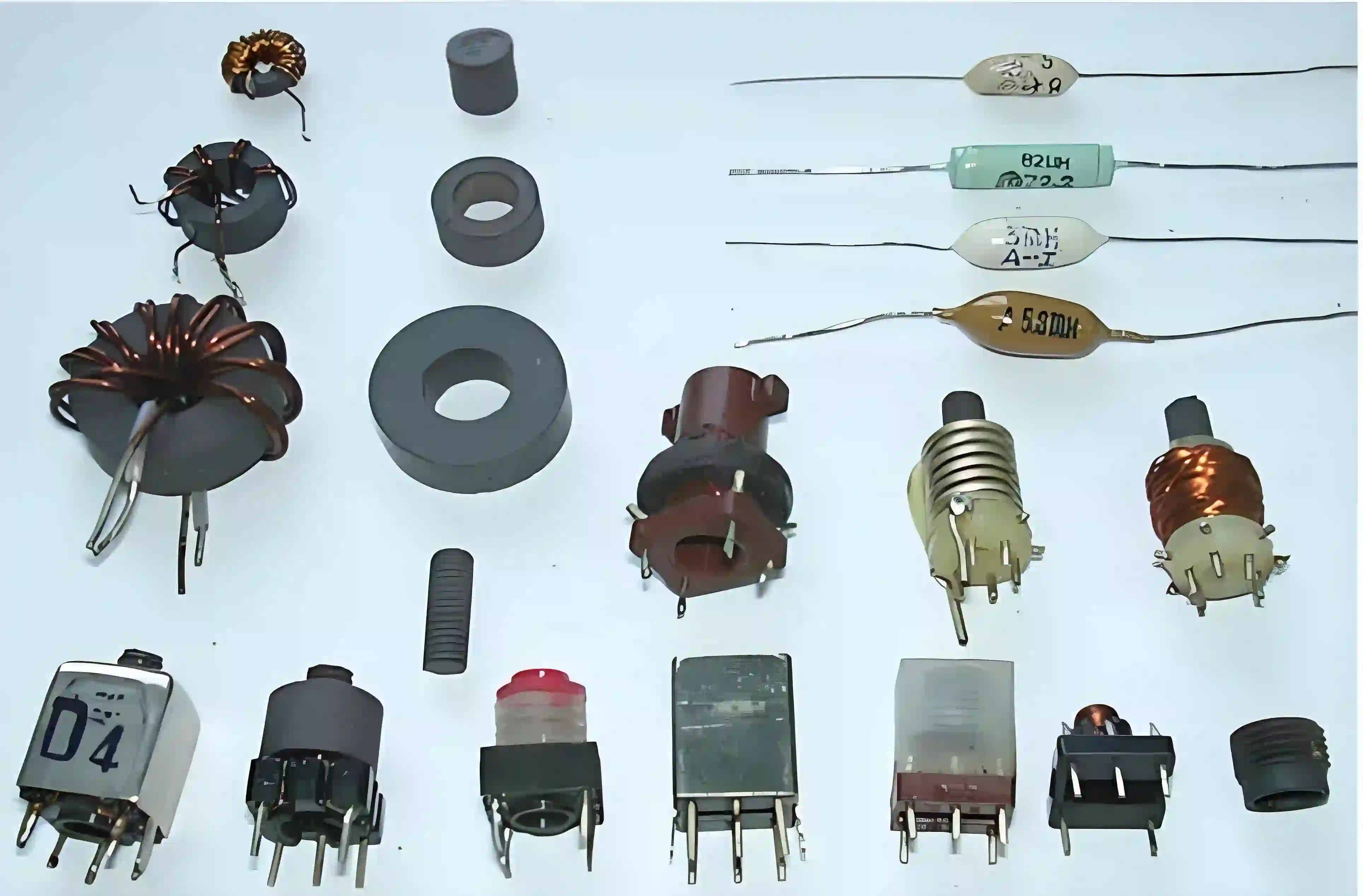
Many through-hole components, such as diodes, transistors, and inductors, have printed codes or markings that indicate their specifications. While each component type has its own system, here are some general tips for reading through-hole component codes:
- Diodes: Look for a band or stripe on one end, which typically marks the cathode (negative side). Part numbers like "1N4148" may also be printed for identification.
- Transistors: These often have a part number printed on the body, such as "2N2222." The orientation of leads (base, collector, emitter) must match the circuit design.
- Inductors: Similar to resistors, they may use color bands or direct value markings in microhenries (μH).
Always refer to a component's datasheet for precise information if the markings are unclear. Datasheets provide detailed specs, pin configurations, and usage guidelines.
Through-Hole Component Polarity: Why It Matters
Polarity refers to the positive and negative sides of a component, and incorrect orientation can damage the part or the entire circuit. Not all through-hole components are polarized, but for those that are, correct placement is essential. Here's how to handle through-hole component polarity:
- Electrolytic Capacitors: As mentioned, the negative side is marked with a stripe or arrow. The positive lead is usually longer. Always align with the PCB markings.
- Diodes: The cathode (negative) is marked with a band. Current flows from anode to cathode, so ensure the direction matches the circuit design.
- LEDs: Similar to diodes, LEDs have a longer lead for the anode (positive) and a shorter lead for the cathode. Some also have a flat edge on the cathode side of the plastic body.
Non-polarized components like resistors and ceramic capacitors can be placed in any direction, making them easier to work with for beginners.
Identifying Axial and Radial Lead Components: What's the Difference?
Through-hole components are categorized by their lead configuration, which affects how they are mounted on a PCB. Understanding the difference between axial and radial lead components is key to identification and placement.
Axial Lead Components
Axial lead components have leads extending from both ends of the component body, running parallel to its axis. Common examples include resistors, diodes, and some capacitors. They are typically laid flat or bent to fit through PCB holes, spanning between two points on the board.
Radial Lead Components
Radial lead components have leads extending from one side of the body, perpendicular to the component's axis. Electrolytic capacitors and some LEDs are examples. They stand upright on the PCB, with leads inserted into adjacent holes.
Identifying axial and radial lead components helps in understanding how to position them on a board and ensures a neat, functional assembly.
Tips for Beginners: Tools and Best Practices for Identification
Identifying through-hole components becomes easier with the right tools and habits. Here are some practical tips to build your skills:
- Use a Multimeter: A multimeter can test resistance, capacitance, and diode polarity if markings are unclear. For example, measuring a resistor might show a value close to 1 kΩ, confirming a color band reading.
- Keep a Reference Chart: Have a resistor color code chart and capacitor code table handy for quick lookups.
- Organize Components: Sort components by type and value in labeled containers to avoid mix-ups during projects.
- Double-Check Polarity: Before soldering polarized components, verify their orientation against the PCB silkscreen or schematic.
- Practice with Kits: Start with beginner electronics kits that include a variety of through-hole components and clear instructions.
Common Mistakes to Avoid in Through-Hole Component Identification
Even with careful attention, beginners can make mistakes. Here are some pitfalls to watch out for:
- Misreading Color Bands: Confusing colors like brown and red can lead to wrong resistance values. Use good lighting and magnification if needed.
- Ignoring Polarity: Installing a polarized capacitor or diode backward can cause failure or explosion. Always check markings.
- Mixing Up Lead Types: Bending axial leads incorrectly or misplacing radial components can make a circuit messy or non-functional.
- Overlooking Voltage Ratings: Using a capacitor with a voltage rating below the circuit's requirement (e.g., a 10V capacitor in a 12V circuit) can lead to breakdown.
Conclusion: Mastering Through-Hole Component Identification
Learning through-hole component identification is a foundational skill for anyone starting in electronics. From through-hole resistor identification using color bands to recognizing through-hole capacitor types and their polarity, each step builds your ability to create reliable circuits. By understanding how to read component codes and distinguish between axial and radial lead components, you'll avoid common errors and gain confidence in your projects.
Start small, practice often, and use the tools and tips provided in this guide to sharpen your skills. With time, identifying and working with through-hole components will become second nature, opening the door to more complex and exciting electronic designs. If you're ready to take the next step, explore resources and services for PCB assembly and prototyping to bring your ideas to life.


