 ALLPCB


In the fast-paced world of electronics manufacturing, achieving reliable surface mount assembly is critical for producing high-quality printed circuit boards (PCBs). The IPC J-STD-001 standard serves as the cornerstone for ensuring excellence in soldering and assembly processes. Whether you're looking for J-STD-001 SMT soldering guidelines, surface mount assembly best practices, reflow soldering J-STD-001 compliance, or J-STD-001 component placement tolerances, this guide will provide actionable insights to elevate your SMT processes. At ALLPCB, we’re committed to helping you master these standards for flawless results.
In this comprehensive blog, we’ll dive deep into the essentials of IPC J-STD-001, explore best practices for surface mount technology (SMT), and share tips to ensure reliability in every assembly. Let’s get started on the path to SMT excellence.
What is IPC J-STD-001 and Why Does It Matter for SMT?
IPC J-STD-001 is a globally recognized standard developed by the Institute of Printed Circuits (IPC) that outlines the requirements for soldered electrical and electronic assemblies. It covers everything from materials and processes to inspection criteria and quality assurance. For manufacturers focusing on SMT, this standard is a blueprint for achieving consistent, reliable results in soldering and component assembly.
Adhering to J-STD-001 ensures that your assemblies meet strict quality benchmarks, reducing the risk of defects like poor solder joints, component misalignment, or thermal damage during reflow soldering. By following these guidelines, manufacturers can improve product reliability, minimize rework costs, and meet customer expectations in industries like aerospace, automotive, and consumer electronics.
Key Benefits of J-STD-001 Compliance
- Enhanced product reliability through standardized soldering and assembly practices.
- Reduced failure rates by addressing common SMT defects like tombstoning or solder bridging.
- Improved traceability and accountability with clear documentation and process control requirements.
- Global acceptance, making it easier to meet client and regulatory demands.

J-STD-001 SMT Soldering Guidelines: Building Strong Connections
Soldering is the heart of SMT assembly, and the J-STD-001 standard provides detailed guidelines to ensure strong, reliable solder joints. These guidelines cover everything from solder alloy selection to thermal profiles during reflow soldering. Let’s break down the key aspects for achieving top-notch soldering results.
1. Selecting the Right Materials
J-STD-001 emphasizes the importance of using compatible materials to avoid issues like intermetallic compound formation or thermal stress. For instance, lead-free solder alloys like SAC305 (Sn96.5Ag3.0Cu0.5) are commonly recommended for their balance of strength and melting point (around 217°C). Ensure that your solder paste, flux, and components are compatible to prevent defects.
2. Controlling Solder Paste Application
Precise stencil printing is critical for applying solder paste. J-STD-001 recommends maintaining stencil thickness between 0.1mm to 0.15mm for most SMT applications to control paste volume. Too much paste can lead to bridging, while too little can cause insufficient joints. Regular inspection of stencil alignment and cleaning is also advised to maintain consistency.
3. Thermal Profile Management
During reflow soldering, maintaining the correct thermal profile is essential for J-STD-001 compliance. The standard suggests a peak temperature of 235-245°C for lead-free solders, with a time above liquidus (TAL) of 30-90 seconds. Overheating can damage components, while underheating may result in cold solder joints. Use a reflow oven with precise temperature control and monitor profiles with thermocouples for accuracy.
Surface Mount Assembly Best Practices: Precision in Every Step
Beyond soldering, achieving reliable SMT assembly requires attention to every stage of the process. Here are some surface mount assembly best practices aligned with J-STD-001 to ensure high-quality outcomes.
1. Component Handling and Storage
Moisture-sensitive devices (MSDs) like ICs and LEDs must be stored in moisture barrier bags with desiccant packs to prevent popcorn cracking during reflow. J-STD-001 specifies following manufacturer recommendations for exposure time, often limiting it to 168 hours at 30°C/60% RH for level 3 components. Always check moisture sensitivity levels (MSL) before assembly.
2. Accurate Component Placement
Precise placement of components is critical to avoid misalignment or tombstoning. Automated pick-and-place machines should be calibrated to achieve placement accuracy within ±0.1mm. J-STD-001 also stresses the importance of verifying component orientation and polarity before soldering to prevent functional failures.
3. Post-Soldering Inspection
After soldering, inspect assemblies for defects like insufficient solder, voids, or cracks. J-STD-001 provides acceptance criteria for solder joint appearance, such as a fillet height of at least 25% of the component termination height for leadless components. Use automated optical inspection (AOI) systems or X-ray imaging for hidden joints under BGAs to ensure quality.

Reflow Soldering J-STD-001 Compliance: Mastering the Heat
Reflow soldering is a critical process in SMT assembly, and adhering to reflow soldering J-STD-001 compliance ensures that components are securely bonded without damage. Let’s explore how to optimize this process for reliability.
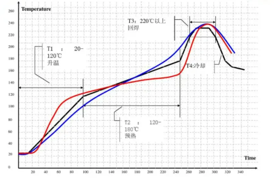
1. Understanding Reflow Zones
A typical reflow profile includes preheat, soak, reflow, and cooling zones. J-STD-001 recommends a preheat rate of 1-3°C per second to prevent thermal shock. The soak zone, typically between 150-200°C for 60-120 seconds, activates flux and evaporates solvents. During the reflow zone, ensure the peak temperature aligns with solder specifications to form strong intermetallic bonds.
2. Avoiding Common Defects
Defects like solder balling or component shifting often occur due to improper reflow settings. J-STD-001 advises maintaining a balanced conveyor speed (typically 0.8-1.2 meters per minute) to ensure even heating. Additionally, use nitrogen atmosphere reflow if oxidation is a concern, especially for fine-pitch components.
3. Documentation and Process Control
J-STD-001 mandates detailed documentation of reflow profiles and regular validation of equipment performance. Keep records of temperature settings, conveyor speeds, and inspection results to demonstrate compliance during audits. Implement statistical process control (SPC) to monitor variations and address issues proactively.
J-STD-001 Component Placement Tolerances: Precision Matters
Component placement accuracy directly impacts the reliability of SMT assemblies. The J-STD-001 component placement tolerances provide clear criteria to ensure components are positioned correctly for optimal soldering and functionality.
1. Acceptable Placement Deviations
According to J-STD-001, placement deviations should not exceed 50% of the pad width for rectangular chip components like resistors and capacitors. For fine-pitch components like QFPs, the tolerance is tighter, often requiring alignment within ±0.05mm to prevent soldering defects. Always refer to the specific class of assembly (Class 1, 2, or 3) as tolerances vary based on product criticality.
2. Impact on Soldering Quality
Misplacement beyond acceptable tolerances can lead to issues like open circuits or shorts. For instance, if a 0402 resistor shifts by more than 0.2mm, it may not form a proper solder joint, leading to reliability issues. Use high-precision placement equipment and vision systems to maintain accuracy during assembly.
3. Design for Manufacturability (DFM)
J-STD-001 encourages collaboration between design and manufacturing teams to optimize PCB layouts for placement accuracy. Ensure pad sizes match component dimensions and provide adequate spacing (at least 0.3mm for 0402 components) to accommodate placement tolerances. Incorporate fiducial marks on the PCB for precise machine alignment.

Common Challenges in SMT Assembly and How J-STD-001 Helps
Even with the best equipment, SMT assembly can face challenges like component tombstoning, solder voids, or thermal stress. J-STD-001 provides solutions by standardizing processes and offering troubleshooting guidance.
1. Tombstoning
Tombstoning occurs when one end of a component lifts during reflow, often due to uneven heating or pad design. J-STD-001 recommends balanced pad sizes and symmetrical thermal profiles to minimize this issue. Preheat components evenly to ensure uniform solder melting.
2. Solder Voids
Voids in solder joints reduce mechanical strength and thermal conductivity. J-STD-001 suggests optimizing reflow profiles to allow outgassing and using low-voiding solder pastes. X-ray inspection can detect voids under BGAs, ensuring they remain within acceptable limits (typically less than 25% of joint area).
3. Thermal Stress
Components like multilayer ceramic capacitors (MLCCs) are prone to cracking under thermal stress. J-STD-001 advises controlled cooling rates (1-4°C per second) after reflow to prevent stress buildup. Use thermal relief designs in PCB layouts to minimize heat concentration.
How ALLPCB Supports Your SMT Excellence
At ALLPCB, we understand the importance of adhering to standards like IPC J-STD-001 to deliver reliable SMT assemblies. Our state-of-the-art facilities are equipped with advanced pick-and-place machines, precision reflow ovens, and AOI systems to ensure compliance at every step. We also provide detailed process documentation and quality reports to give you peace of mind.
Whether you’re prototyping a new design or scaling up for mass production, our team is ready to support your SMT needs with expertise and efficiency. Trust us to help you achieve flawless assemblies that meet the highest industry standards.
Conclusion: Elevate Your SMT Assembly with J-STD-001
Achieving excellence in surface mount assembly requires a commitment to quality, precision, and standardization. By following the J-STD-001 SMT soldering guidelines, implementing surface mount assembly best practices, ensuring reflow soldering J-STD-001 compliance, and adhering to J-STD-001 component placement tolerances, you can build reliable, high-performing PCBs that stand the test of time.
With the right processes and a trusted partner like ALLPCB, SMT excellence is within reach. Implement these strategies in your next project to minimize defects, improve reliability, and exceed customer expectations. Let’s build the future of electronics together, one perfect solder joint at a time.


