 ALLPCB


As an electrical engineer working on noise-sensitive circuits, you’re likely searching for the best ways to select a voltage regulator that minimizes noise and ensures clean power delivery. Whether you’re designing for audio applications, precision instrumentation, or RF systems, the right voltage regulator can make or break your project. In this comprehensive guide, we’ll dive into optimizing voltage regulator selection for noise-sensitive circuits, focusing on voltage regulator noise reduction PCB, low noise voltage regulator for audio, voltage regulator ripple rejection SMT, and minimizing EMI voltage regulator. Let’s explore how to achieve precision power delivery with actionable tips and technical insights tailored for engineers like you.
Why Voltage Regulator Selection Matters for Noise-Sensitive Circuits
In noise-sensitive circuits, even small fluctuations in power supply can lead to significant performance issues. Think about an audio amplifier where power supply noise translates directly into audible hums or distortion, or a high-precision sensor where ripple affects measurement accuracy. The voltage regulator is your first line of defense against these problems. Choosing the right one—and integrating it properly into your PCB design—ensures stable, clean power delivery.
Key considerations include noise output, ripple rejection, and electromagnetic interference (EMI). A poorly chosen regulator can introduce noise levels as high as 100 μV RMS or fail to suppress input ripple, directly impacting circuit performance. In this post, we’ll break down the types of regulators, their specs, and design strategies to help you make informed decisions.
Understanding Noise in Voltage Regulators: The Basics
Before diving into selection criteria, let’s clarify what “noise” means in the context of voltage regulators. Noise refers to unwanted voltage fluctuations at the regulator’s output, often measured in microvolts RMS (root mean square) over a specific frequency range, like 10 Hz to 100 kHz. For noise-sensitive applications, you’ll want a regulator with output noise below 10 μV RMS to avoid interference with delicate signals.
Ripple, on the other hand, is the residual AC component from the input power source that the regulator fails to filter out. A regulator’s ability to suppress this is quantified by its Power Supply Rejection Ratio (PSRR), expressed in decibels (dB). A PSRR of 60 dB or higher is often necessary for audio or precision circuits to ensure input fluctuations don’t affect the output.
EMI is another concern, especially in high-frequency designs. Regulators, particularly switching types, can generate EMI that interferes with nearby components. Minimizing EMI voltage regulator design involves both component selection and PCB layout techniques, which we’ll cover later.
Types of Voltage Regulators for Noise-Sensitive Circuits
There are two main categories of voltage regulators to consider: linear and switching. Each has its pros and cons for noise-sensitive applications. Let’s break them down.
Linear Voltage Regulators: The Low-Noise Champion
Linear regulators, such as Low Dropout (LDO) regulators, are often the go-to choice for noise-sensitive circuits. They work by dissipating excess voltage as heat, resulting in a very clean output with minimal noise—often below 5 μV RMS for high-performance models like the Texas Instruments TPS7A47.
For low noise voltage regulator for audio applications, LDOs shine due to their high PSRR (up to 70 dB at 1 kHz) and low output noise. However, they’re less efficient at higher currents or large voltage drops, leading to heat dissipation challenges. If your design operates at 3.3V with a 5V input and draws under 500 mA, an LDO is ideal.
Switching Voltage Regulators: Efficiency with Trade-Offs
Switching regulators, like buck or boost converters, are far more efficient, especially for high-current or wide voltage differential designs. However, they introduce switching noise, typically in the range of 50-100 μV RMS, and can generate significant EMI due to their high-frequency operation (often 100 kHz to 2 MHz).
For noise-sensitive circuits, switching regulators are often paired with a post-regulation LDO to clean up the output. This hybrid approach balances efficiency and noise but adds complexity and cost. If EMI is a concern, look for switching regulators with spread-spectrum frequency modulation to reduce peak interference.
Key Specifications for Voltage Regulator Selection
When selecting a voltage regulator for noise-sensitive circuits, focus on these critical specifications. Understanding these will help you match the regulator to your application’s needs.
Output Noise
As mentioned, output noise is critical. For audio circuits or precision analog designs, aim for regulators with noise levels below 10 μV RMS. Check the datasheet for noise performance across the frequency band relevant to your application. For instance, audio circuits are most sensitive to noise between 20 Hz and 20 kHz.
Power Supply Rejection Ratio (PSRR)
For voltage regulator ripple rejection SMT designs, PSRR is a key metric. A higher PSRR means better rejection of input ripple. Look for values above 60 dB at your operating frequency. For example, the Analog Devices LT3045 offers a PSRR of 76 dB at 1 kHz, making it excellent for rejecting power supply noise in surface-mount technology (SMT) applications.
Load and Line Regulation
Load regulation indicates how much the output voltage changes with varying load current, while line regulation shows the effect of input voltage changes. For precision circuits, aim for load regulation below 0.1% and line regulation below 0.01% to ensure stability under dynamic conditions.
Dropout Voltage
For LDOs, dropout voltage—the minimum input-to-output voltage difference needed for regulation—matters. A lower dropout (e.g., 0.2V for the Nisshinbo NR1644) allows operation closer to the output voltage, improving efficiency in low-voltage designs.
PCB Layout Strategies for Voltage Regulator Noise Reduction
Even the best voltage regulator can underperform if the PCB layout isn’t optimized. Poor layout can introduce noise, degrade ripple rejection, and amplify EMI. Here are proven strategies for voltage regulator noise reduction PCB design.
Minimize Ground Loops
Ground loops are a common source of noise in PCB designs. Use a solid ground plane and ensure the regulator’s ground pin connects directly to it with minimal trace length. Avoid sharing ground paths between noisy digital circuits and sensitive analog sections. If possible, split the ground plane into analog and digital sections, connecting them at a single point near the regulator.
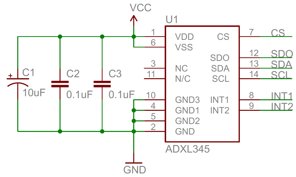
Place Decoupling Capacitors Close to Pins
Decoupling capacitors filter high-frequency noise at the regulator’s input and output. Place a 0.1 μF ceramic capacitor as close as possible to the input and output pins—ideally within 2 mm. For LDOs, check the datasheet for recommended output capacitor values (often 1-10 μF) to ensure stability, as some regulators require specific capacitance and ESR (equivalent series resistance) for proper operation.
Shorten Power Traces
Long power traces act as antennas, picking up or radiating noise. Route input and output traces as short and wide as possible to reduce resistance and inductance. For SMT designs, use vias sparingly near the regulator to avoid adding inductance.
Minimizing EMI in Voltage Regulator Designs
For minimizing EMI voltage regulator performance, both component selection and layout play a role. Switching regulators are notorious for EMI due to their fast-switching edges, but even linear regulators can pick up or radiate interference if not designed carefully.
Choose Low-EMI Regulators
Look for switching regulators with features like spread-spectrum modulation, which randomizes the switching frequency to reduce EMI peaks. The Texas Instruments TPS54202, for example, includes this feature and is designed for low EMI in noise-sensitive applications.
Use Shielding and Filtering
Add ferrite beads or inductors at the regulator input to filter high-frequency EMI from the power source. For sensitive designs, consider shielding the regulator area with a metal enclosure or guard ring on the PCB to contain radiated interference.
Optimize Switching Node Layout
For switching regulators, the switching node (where the inductor connects) is a major EMI source. Keep this node’s area small and avoid routing sensitive traces nearby. Place the inductor and output capacitor close to the regulator to minimize loop area.
Application-Specific Tips: Low Noise Voltage Regulator for Audio
Audio circuits are particularly sensitive to power supply noise, as it can manifest as hums, buzzes, or reduced dynamic range. When selecting a low noise voltage regulator for audio, prioritize ultra-low noise LDOs with high PSRR in the audible frequency range (20 Hz to 20 kHz).
For example, the Linear Technology LT3042 offers a noise level of just 0.8 μV RMS and a PSRR of 79 dB at 1 kHz, making it ideal for powering audio preamps or DACs. Additionally, use separate regulators for analog and digital sections of an audio circuit to prevent digital switching noise from contaminating the analog power supply.
In my experience designing a high-fidelity audio board, I found that pairing an LDO with a well-designed ground plane reduced audible noise by over 30 dB compared to a basic switching regulator setup. It’s worth the extra effort to isolate power domains and test the noise floor with an audio analyzer during prototyping.
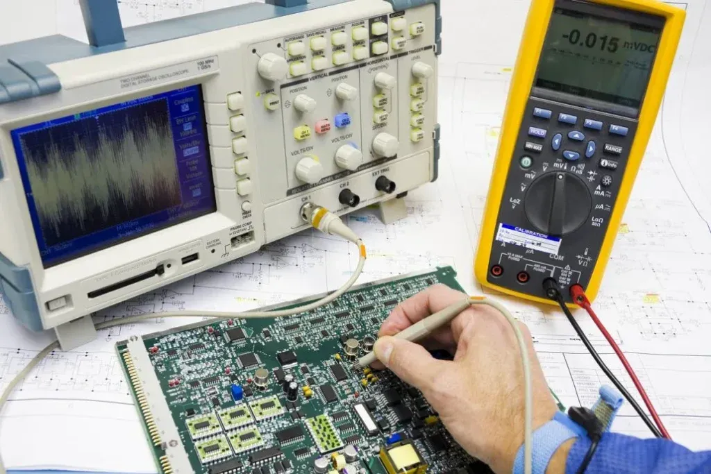
Testing and Validation: Ensuring Noise Performance
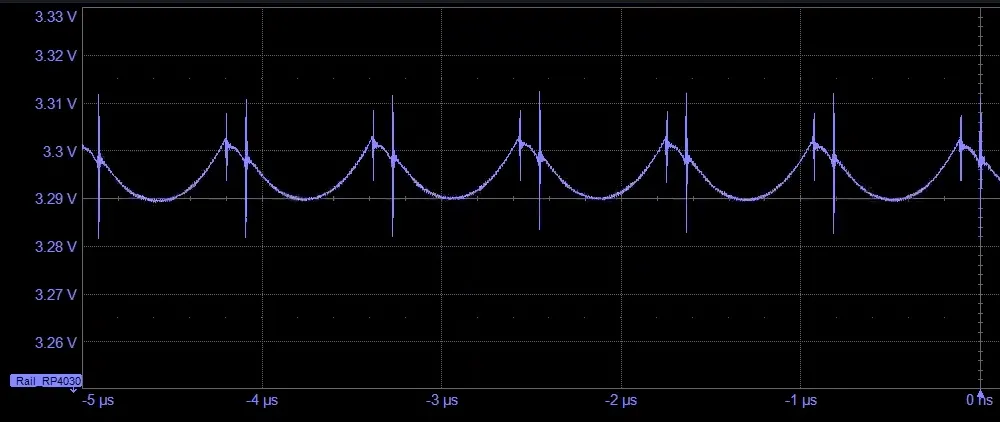
After selecting a regulator and designing the PCB, testing is crucial. Use an oscilloscope to measure output noise and ripple under typical operating conditions. Set the scope to AC coupling with a 20 MHz bandwidth limit to avoid picking up irrelevant high-frequency noise.
For EMI, use a spectrum analyzer to check for spurious emissions around the regulator’s switching frequency (if applicable). If noise or EMI exceeds acceptable levels—say, above 10 μV RMS for an audio circuit—revisit your layout or add additional filtering components like a pi-filter (inductor-capacitor-inductor) at the input.
Conclusion: Building Precision Power for Your PCB
Optimizing voltage regulator selection for noise-sensitive circuits is a multi-faceted challenge, but with the right knowledge, you can achieve precision power delivery. Focus on low-noise regulators like LDOs for applications such as audio, prioritize specs like PSRR and output noise, and invest time in PCB layout to ensure voltage regulator noise reduction PCB performance. For voltage regulator ripple rejection SMT designs, choose components with high PSRR and follow best practices for decoupling. Finally, tackle minimizing EMI voltage regulator issues with thoughtful layout and EMI-aware component choices.


