 ALLPCB


Solder paste printing is a critical step in Surface Mount Technology (SMT) assembly, directly impacting the quality and yield of printed circuit board (PCB) production. By fine-tuning elements like stencil design, squeegee pressure, and solder paste viscosity, manufacturers can achieve consistent, high-quality results and minimize defects. In this comprehensive guide, we’ll dive deep into the essentials of optimizing solder paste printing for SMT assembly, providing actionable insights to enhance your production process.
Why Solder Paste Printing Matters in SMT Assembly
In SMT assembly, solder paste printing lays the foundation for attaching components to the PCB. This process involves applying a precise layer of solder paste—a mixture of tiny solder particles and flux—onto the board’s pads through a stencil. If done correctly, it ensures strong, reliable connections during reflow soldering. However, errors in printing can lead to defects like bridging, insufficient solder, or tombstoning, which compromise the final product’s performance.
Optimizing solder paste printing isn’t just about avoiding defects; it’s about maximizing yield, reducing waste, and improving efficiency. With the right techniques, you can achieve consistent results even with complex designs or high-density boards. Let’s explore the key factors that influence this process and how to fine-tune them for success.
Understanding the Basics of Solder Paste Printing
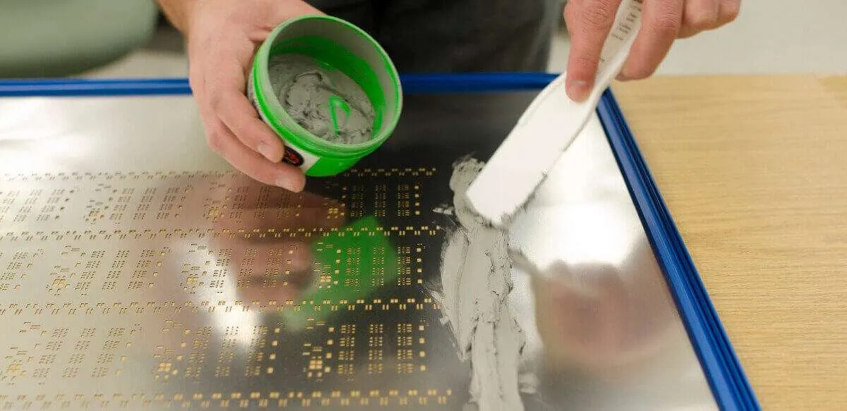
Before diving into optimization techniques, it’s important to grasp the fundamentals of solder paste printing. The process uses a stencil—a thin metal sheet with openings corresponding to the PCB’s pads—to control where the paste is deposited. A squeegee moves across the stencil, pushing the paste through these openings onto the board below.
The goal is to deposit the right amount of paste with uniform thickness and shape. Too much paste can cause bridging between pads, while too little can result in weak solder joints. Achieving this balance depends on several interconnected factors, which we’ll break down in the following sections.
Key Components of the Printing Process
- Stencil: Acts as a template for paste application, determining the precision of deposition.
- Squeegee: A blade that forces paste through the stencil openings, with pressure and speed playing a major role.
- Solder Paste: The material itself, with properties like viscosity affecting how it flows and adheres.
- Printer Settings: Parameters like print speed and separation distance, which must be adjusted for consistency.
By optimizing each of these elements, you can significantly improve the outcome of your SMT assembly process.
Stencil Design: The Foundation of Precision
Stencil design is arguably the most critical factor in solder paste printing. A well-designed stencil ensures that the paste is applied accurately to each pad, matching the component requirements. Poor design, on the other hand, can lead to inconsistent deposits or defects.
Key Considerations in Stencil Design
- Aperture Size and Shape: The openings in the stencil must match the pad size on the PCB. For fine-pitch components, smaller apertures (often 0.1 mm to 0.2 mm smaller than the pad) help control paste volume and prevent excess deposition. Rounded corners on apertures can also improve paste release, reducing the risk of clogging.
- Stencil Thickness: Typically ranging from 0.1 mm to 0.15 mm for standard SMT applications, the thickness determines the volume of paste deposited. Thicker stencils deposit more paste, which may be necessary for larger components, while thinner stencils are better for fine-pitch designs.
- Material and Fabrication: Stainless steel stencils, often laser-cut for precision, offer durability and accuracy. Laser-cut stencils provide smoother aperture walls, aiding in clean paste release compared to chemically etched alternatives.
Pro Tip: For high-density boards with 0201 components (0.6 mm x 0.3 mm), consider using a step-down stencil. This design varies thickness across different areas, allowing precise control over paste volume for both small and large pads on the same board.
Squeegee Pressure: Striking the Right Balance
Squeegee pressure is another vital parameter in achieving uniform solder paste deposition. The squeegee blade pushes the paste through the stencil openings, and the force applied directly affects the quality of the print.
Optimizing Squeegee Pressure
- Pressure Settings: Too much pressure can cause the stencil to bend or scoop out paste from the apertures, leading to insufficient deposits. Too little pressure may result in incomplete filling of apertures. A typical pressure range for standard SMT printing is between 0.5 kg to 1.5 kg per centimeter of squeegee length, depending on stencil thickness and paste type.
- Squeegee Angle: The angle of the squeegee, often set between 45° and 60°, influences how the paste rolls across the stencil. A steeper angle reduces the risk of paste smearing but may require higher pressure.
- Print Speed: Speed and pressure go hand in hand. A speed of 20 mm to 70 mm per second is common, but slower speeds (closer to 20 mm/s) are better for fine-pitch applications as they allow more time for paste to fill small apertures.
Regularly inspecting the squeegee blade for wear is also essential. A damaged or worn blade can create uneven pressure, leading to inconsistent prints. Replace blades as needed to maintain quality.
Solder Paste Viscosity: Getting the Flow Right
Solder paste viscosity determines how easily the paste flows through the stencil and adheres to the PCB pads. It’s influenced by the paste’s composition, including the ratio of solder particles to flux, as well as environmental factors like temperature.
Factors Affecting Solder Paste Viscosity
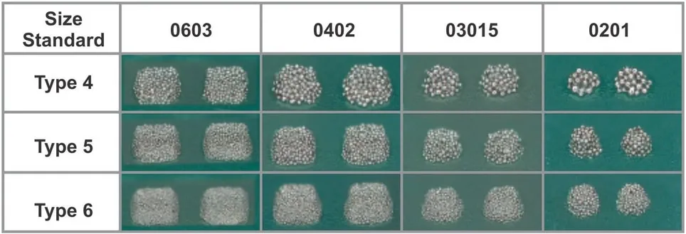
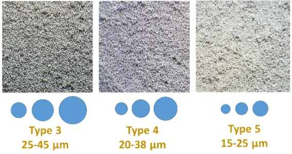
- Paste Type: Solder pastes are categorized by particle size, often referred to as Type 3, Type 4, or Type 5, with smaller particles (like Type 5) used for finer pitches. Smaller particles generally result in lower viscosity, making the paste easier to print for high-density designs.
- Temperature Control: Viscosity decreases as temperature rises. Ideally, store solder paste at 2°C to 10°C before use, and let it reach room temperature (around 25°C) before printing to avoid condensation issues. Printing at a controlled temperature ensures consistent flow.
- Working Life: Once opened, solder paste has a limited working life (often 4 to 8 hours at room temperature) before viscosity changes due to solvent evaporation. Use paste within this window to maintain print quality.
For optimal results, always check the manufacturer’s specifications for viscosity, typically measured in Pascal-seconds (Pa·s), with values ranging from 800 to 1200 Pa·s for standard SMT pastes. Adjust printer settings if you notice the paste is too thick (hard to push through apertures) or too thin (causing slumping after printing).
SMT Optimization: Tying It All Together
While stencil design, squeegee pressure, and solder paste viscosity are crucial, true SMT optimization requires a holistic approach. Each parameter interacts with the others, and fine-tuning one often means adjusting the rest. Here are some overarching strategies to boost your SMT assembly yield through optimized printing.
Process Control and Monitoring
Use automated inspection systems, such as 2D or 3D Solder Paste Inspection (SPI) machines, to measure paste volume, height, and alignment after printing. SPI can detect issues like insufficient paste (below 80% of target volume) or misalignment (offset by more than 25% of pad width), allowing real-time adjustments. Studies show that implementing SPI can reduce soldering defects by up to 70% in high-volume production.
Environmental Conditions
Maintain a controlled environment in your production area. Ideal conditions are a temperature of 20°C to 25°C and humidity of 40% to 60%. High humidity can cause paste to absorb moisture, altering viscosity, while low humidity may lead to static buildup, affecting component placement.
Regular Maintenance
Clean stencils after every 5 to 10 prints to prevent paste buildup in apertures, which can cause defects. Use appropriate cleaning solutions and automated under-stencil wiping systems for efficiency. Also, calibrate your printer regularly to ensure consistent squeegee pressure and alignment.
Common Challenges and Solutions in Solder Paste Printing
Even with optimized settings, challenges can arise during solder paste printing. Below are some common issues and how to address them.
- Bridging: Caused by excess paste or poor stencil design. Reduce squeegee pressure or adjust aperture size to control paste volume.
- Insufficient Paste: Often due to low pressure or clogged apertures. Increase pressure slightly or clean the stencil more frequently.
- Solder Balls: Result from paste slumping or moisture in the paste. Ensure proper storage conditions and check paste viscosity before use.
- Poor Release: Happens when paste sticks to the stencil instead of transferring to the pad. Use stencils with polished apertures or adjust separation speed (typically 0.5 mm/s to 3 mm/s) during printing.
By systematically addressing these issues, you can maintain high yield and avoid costly rework in your SMT assembly line.
Conclusion: Achieving High-Yield SMT Assembly Through Optimization
Optimizing solder paste printing is the cornerstone of high-yield SMT assembly. By focusing on stencil design, squeegee pressure, and solder paste viscosity, you can create a robust printing process that minimizes defects and maximizes efficiency. Combine these with broader SMT optimization strategies like process monitoring and environmental control for the best results.
Every detail matters in PCB production, from the thickness of your stencil to the temperature of your workspace. Take the time to test and adjust your settings, leveraging tools like SPI to ensure consistency. With these practices in place, you’ll be well on your way to achieving reliable, high-quality SMT assembly outcomes.
At ALLPCB, we’re committed to supporting your manufacturing journey with resources and expertise. Implement these solder paste printing optimizations in your next project and see the difference in your production yield.


