 ALLPCB


Reflow soldering is a critical process in PCB manufacturing, and mastering the reflow soldering temperature profile is key to achieving high-quality solder joints and reliable electronic assemblies. Whether you're an engineer or a hobbyist, understanding the reflow profile optimization, reflow zones, and temperature profiling can make or break your project. In this comprehensive guide, we’ll walk you through the essentials of the reflow soldering temperature profile, breaking down each zone—preheat, soak, reflow, and cooling—and providing actionable tips for success.
At its core, a reflow soldering temperature profile is a carefully controlled temperature curve that ensures solder paste melts, wets the components and pads, and solidifies without damaging parts or creating defects. Let’s dive into the details of each zone and how to optimize your reflow process for the best results.
What Is a Reflow Soldering Temperature Profile?
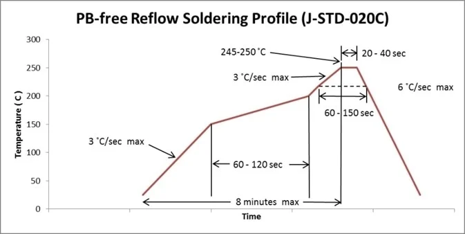
A reflow soldering temperature profile is a time-temperature graph that dictates how a PCB assembly is heated and cooled during the reflow soldering process. This profile is crucial in surface mount technology (SMT) as it ensures that solder paste transitions through various stages—activation, melting, and solidification—without causing thermal stress to components or creating soldering defects like tombstoning or voids.
The profile is typically divided into four main zones: the preheat zone, soak zone, reflow zone, and cooling zone. Each zone has a specific purpose and temperature range, tailored to the type of solder paste (lead-free or leaded) and the components on the board. Proper temperature profiling prevents issues like overheating, insufficient soldering, or component damage, ensuring reliable and consistent results.
Why Is Reflow Profile Optimization Important?
Optimizing your reflow soldering temperature profile is essential for achieving consistent, high-quality solder joints. A poorly designed profile can lead to problems such as:
- Insufficient wetting, causing weak or incomplete solder joints.
- Thermal shock to components due to rapid temperature changes.
- Solder defects like bridging, balling, or voids.
- Component misalignment or damage from excessive heat.
By fine-tuning the temperature profile, you can minimize these risks, improve production efficiency, and ensure the longevity of your PCB assemblies. Reflow profile optimization also accounts for variables like board size, component density, and thermal mass, which all influence how heat is distributed during soldering.
Breaking Down the Reflow Soldering Zones
Each zone in the reflow soldering process plays a unique role in ensuring a successful outcome. Below, we’ll explore the purpose, temperature ranges, and duration of the preheat zone, soak zone, reflow zone, and cooling zone, along with tips for optimizing each stage.
1. Preheat Zone: Setting the Foundation
The preheat zone is the first stage of the reflow soldering temperature profile. Its primary goal is to gradually raise the temperature of the PCB assembly from room temperature to a level where the flux in the solder paste becomes active. This zone prevents thermal shock to components and ensures even heat distribution across the board.
Key Parameters:
- Temperature Range: Typically 25°C to 150°C for leaded solder and up to 180°C for lead-free solder.
- Duration: 60 to 90 seconds, depending on the board’s thermal mass.
- Temperature Rise Rate: 1.5°C to 3°C per second to avoid thermal stress.
In this zone, the solvent in the solder paste begins to evaporate, and the flux starts to clean the surfaces of the pads and component leads by removing oxides. If the temperature rises too quickly, it can cause splattering of the solder paste or uneven heating, leading to defects. Conversely, a slow rise can result in excessive flux evaporation, reducing its effectiveness in later stages.
Optimization Tip: Adjust the preheat duration based on the size and complexity of your PCB. For larger boards with high thermal mass, extend the preheat time slightly to ensure uniform heating. Monitor the temperature rise rate to keep it below 3°C per second for sensitive components.
2. Soak Zone: Activating the Flux
The soak zone, sometimes called the thermal soak or pre-reflow zone, maintains a steady temperature to fully activate the flux in the solder paste. This stage ensures that the flux removes oxides and prepares the surfaces for soldering while allowing the PCB and components to reach thermal equilibrium.
Key Parameters:
- Temperature Range: 150°C to 200°C for leaded solder; 180°C to 220°C for lead-free solder.
- Duration: 60 to 120 seconds.
- Temperature Rise Rate: Minimal, often near 0°C per second, to maintain stability.
During the soak zone, the flux works to clean the metal surfaces, ensuring proper wetting when the solder melts. This stage also helps minimize temperature differences across the board, especially for assemblies with varying component sizes or thermal masses. If the soak time is too short, the flux may not activate fully, leading to poor soldering. If it’s too long, the flux can evaporate excessively, reducing its effectiveness.
Optimization Tip: For boards with mixed thermal mass (e.g., small and large components), extend the soak time slightly to ensure all areas reach the target temperature. Avoid exceeding 120 seconds to prevent flux degradation.
3. Reflow Zone: Melting the Solder
The reflow zone is the heart of the soldering process, where the temperature peaks to melt the solder paste, forming strong, reliable joints between components and pads. This stage requires precise control to ensure the solder melts completely without overheating the components.
Key Parameters:
- Temperature Range: 210°C to 240°C for leaded solder; 240°C to 260°C for lead-free solder.
- Peak Temperature: Should be 20°C to 40°C above the solder’s melting point (e.g., 217°C for common lead-free solders, so peak at 240°C to 250°C).
- Time Above Liquidus (TAL): 30 to 60 seconds to ensure proper wetting and joint formation.
- Duration: Total time in reflow zone is typically 30 to 90 seconds.
In this zone, the solder paste transitions from a solid to a liquid state, wetting the pads and component leads to form a metallurgical bond. The time above liquidus (TAL) is critical—too short, and the solder may not fully wet the surfaces; too long, and components may suffer thermal damage or excessive intermetallic growth, weakening the joint.
Optimization Tip: Use a thermocouple or profiling tool to measure the actual temperature on your PCB, as oven settings may not reflect the true board temperature. Adjust the peak temperature and TAL based on the solder paste manufacturer’s recommendations, typically found in the product datasheet.
4. Cooling Zone: Solidifying the Solder
The cooling zone is the final stage of the reflow soldering temperature profile, where the molten solder solidifies to form permanent joints. Controlled cooling is essential to prevent thermal stress, component damage, or the formation of brittle intermetallic compounds.
Key Parameters:
- Temperature Range: From peak temperature down to below 50°C.
- Cooling Rate: 2°C to 4°C per second for lead-free solder; slightly slower for leaded solder to avoid thermal shock.
- Duration: 30 to 60 seconds, depending on the cooling method (forced air or natural).
Rapid cooling can cause thermal stress, leading to cracked solder joints or component failure, while slow cooling can result in grainy or weak joints due to prolonged exposure to high temperatures. The ideal cooling rate balances speed and control, ensuring a fine-grained solder structure for maximum strength.
Optimization Tip: Use forced air cooling in the oven if available, but ensure the rate does not exceed 4°C per second for lead-free solder. For small batches or prototype boards, allow natural cooling outside the oven, but avoid sudden temperature drops (e.g., placing the board on a cold surface).
Related Reading: Optimizing Reflow Soldering Temperature for Solder Paste
How to Optimize Your Reflow Soldering Temperature Profile
Reflow profile optimization is not a one-size-fits-all process. It requires careful adjustment based on your specific PCB design, components, and solder paste. Here are actionable steps to fine-tune your temperature profiling:
- Start with Manufacturer Guidelines: Refer to the solder paste datasheet for recommended temperature ranges, TAL, and cooling rates. Lead-free solders typically require higher temperatures (240°C to 260°C peak) compared to leaded solders (210°C to 240°C).
- Use a Profiling Tool: Attach thermocouples to critical points on your PCB (e.g., near large components or high-density areas) to measure the actual temperature profile. Compare this data to your oven settings and adjust as needed.
- Account for Thermal Mass: Larger boards or those with heavy copper layers absorb more heat, requiring longer preheat and soak times. Conversely, smaller boards may need shorter durations to avoid overheating.
- Test and Iterate: Run a small batch of boards with your initial profile, inspect the solder joints for defects (e.g., voids, bridging), and tweak the profile accordingly. Use X-ray or visual inspection tools for detailed analysis.
- Consider Component Sensitivity: Check the maximum temperature ratings of sensitive components (e.g., LEDs, capacitors) in their datasheets. Ensure the peak temperature and TAL do not exceed these limits.
By following these steps, you can create a customized reflow soldering temperature profile that minimizes defects and maximizes reliability for your specific assembly.
Common Challenges in Reflow Soldering and How to Solve Them
Even with a well-designed temperature profile, issues can arise during reflow soldering. Below are some common problems and their solutions:
- Tombstoning: This occurs when one end of a component lifts off the pad due to uneven heating. Solution: Extend the soak zone to ensure uniform temperature across the board.
- Solder Voids: Gas trapped in the solder joint creates voids, weakening the connection. Solution: Optimize the preheat and soak zones to allow proper outgassing of flux solvents.
- Insufficient Wetting: Solder fails to bond properly to pads or leads. Solution: Increase the TAL slightly or check for contamination on the PCB surface.
- Component Damage: Overheating can crack or degrade components. Solution: Reduce the peak temperature or shorten the reflow zone duration.
Regularly monitoring and adjusting your reflow profile can prevent these issues, ensuring consistent, high-quality results.
Related Reading: Reflow Soldering Secrets: Achieving Perfect SMT Joints Every Time
Conclusion: Take Control of Your Reflow Soldering Process
Mastering the reflow soldering temperature profile is a game-changer for anyone involved in PCB assembly. By understanding and optimizing each zone—preheat, soak, reflow, and cooling—you can achieve reliable solder joints, minimize defects, and protect your components from thermal stress. Temperature profiling is both an art and a science, requiring careful measurement, testing, and adjustment to suit your specific board and components.
With the step-by-step guidance provided in this blog, you’re equipped to tackle reflow profile optimization with confidence. Whether you’re working on a small prototype or a large-scale production run, a well-designed reflow soldering temperature profile will elevate the quality of your assemblies. Start by following the manufacturer’s recommendations, use profiling tools to gather real data, and fine-tune your process for the best results.


