 ALLPCB


If you're new to PCB design and wondering how to create an easy PCB layout or a simple circuit board design while adhering to industry standards, you're in the right place. This guide will walk you through the essentials of PCB design for beginners, focusing on key ASTM standards that ensure quality and reliability. We'll break down complex ideas into manageable steps, offering practical tips and insights to help hobbyists and aspiring engineers master circuit design.
In the detailed sections below, we'll explore what PCB design entails, why ASTM standards matter, and how to apply them in your projects. Whether you're working on a small hobby project or aiming to build a professional-grade board, this PCB design tutorial will provide a solid foundation for success.
What Is PCB Design and Why Is It Important?
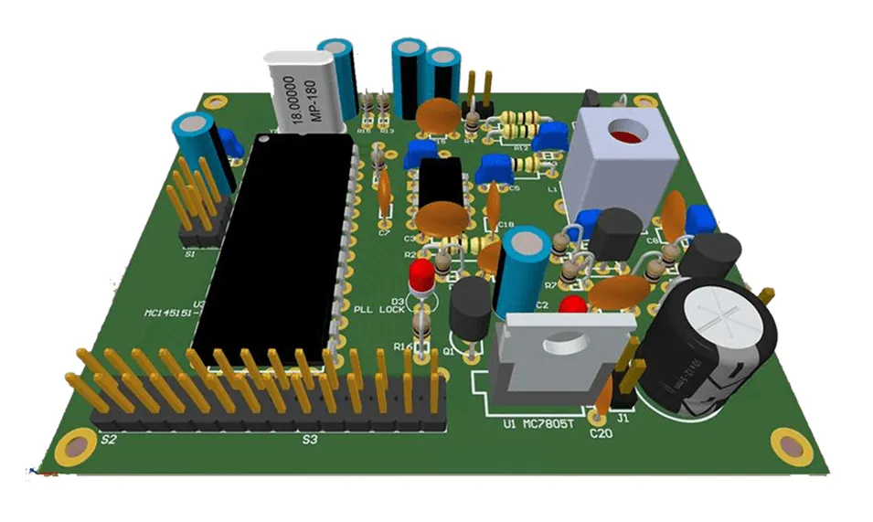
Printed Circuit Board (PCB) design is the process of creating a layout for electronic components to be mounted and connected on a board. It acts as the backbone of almost every electronic device, from smartphones to home appliances. For beginners, PCB design might seem daunting, but with the right approach, it becomes an exciting and rewarding skill.
A well-designed PCB ensures that your circuit works efficiently, avoids interference, and lasts longer. Poor design, on the other hand, can lead to issues like signal loss, overheating, or even complete failure. This is where standards, such as those from ASTM International, come into play. They provide guidelines to ensure safety, performance, and compatibility in your designs.
Understanding ASTM Standards in PCB Design
ASTM International develops standards that cover a wide range of industries, including electronics. For PCB design, these standards help ensure that materials, processes, and final products meet specific quality benchmarks. As a beginner, you don't need to know every standard, but familiarizing yourself with a few key ones can make a big difference in your projects.
ASTM standards related to PCB design often focus on materials, testing methods, and performance criteria. They help you choose the right materials for your board, ensure proper soldering techniques, and test your design for durability. By following these guidelines, you can avoid common pitfalls and build reliable circuits.
Key ASTM Standards for Beginners
Here are a few ASTM standards that are particularly relevant for PCB design and circuit design for hobbyists:
- ASTM B545: Covers the specification for electrodeposited coatings of tin, often used in PCB soldering. This standard ensures that the tin coating on your board’s pads is durable and provides good solderability. For example, a typical thickness for tin plating might range from 0.0001 to 0.0003 inches, depending on the application.
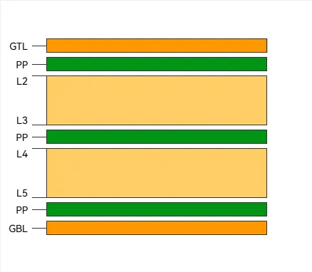
- ASTM D709: Focuses on laminated thermosetting materials, which are often used as the base for PCBs. It classifies materials based on their electrical and mechanical properties, helping you select a substrate that can handle your circuit’s needs, such as withstanding temperatures up to 130°C for standard FR-4 boards.
- ASTM F1896: Provides test methods for determining the electrical resistivity of conductive materials on PCBs. This is crucial for ensuring that traces can carry current without excessive resistance, which could lead to heat buildup. For instance, a copper trace with a resistivity of around 1.68 x 10^-8 ohm-meters is ideal for most low-power designs.
These standards might sound technical, but they boil down to practical choices: picking the right materials, ensuring good connections, and testing your board for reliability. As a beginner, start by understanding the basics of these standards and apply them as you grow more comfortable with PCB design.
Getting Started with PCB Design for Beginners
Now that you understand the importance of ASTM standards, let’s dive into the practical steps of creating a simple circuit board design. This PCB design tutorial will guide you through the process, focusing on easy PCB layout techniques that even hobbyists can follow.
Step 1: Define Your Circuit’s Purpose
Before you start designing, know what your circuit is supposed to do. Are you building a simple LED blinker, a power supply, or a sensor module? Write down the components you’ll need, such as resistors, capacitors, and microcontrollers. This step helps you avoid overcomplicating your design and ensures you only include what’s necessary.
For example, if you’re designing a basic LED circuit, you might need a 220-ohm resistor to limit current to a 5V LED, along with a small power source. Keep your schematic simple at first, focusing on functionality over complexity.
Step 2: Create a Schematic Diagram
A schematic is a blueprint of your circuit, showing how components connect without worrying about the physical layout. Use free or open-source design software to draw your schematic. Place components logically, connecting them with wires to show the flow of electricity.
Double-check your connections to avoid errors. For instance, ensure that a capacitor’s polarity is correct if it’s an electrolytic type, as reversing it could damage your circuit. Once your schematic is ready, you’re set to move to the layout phase.
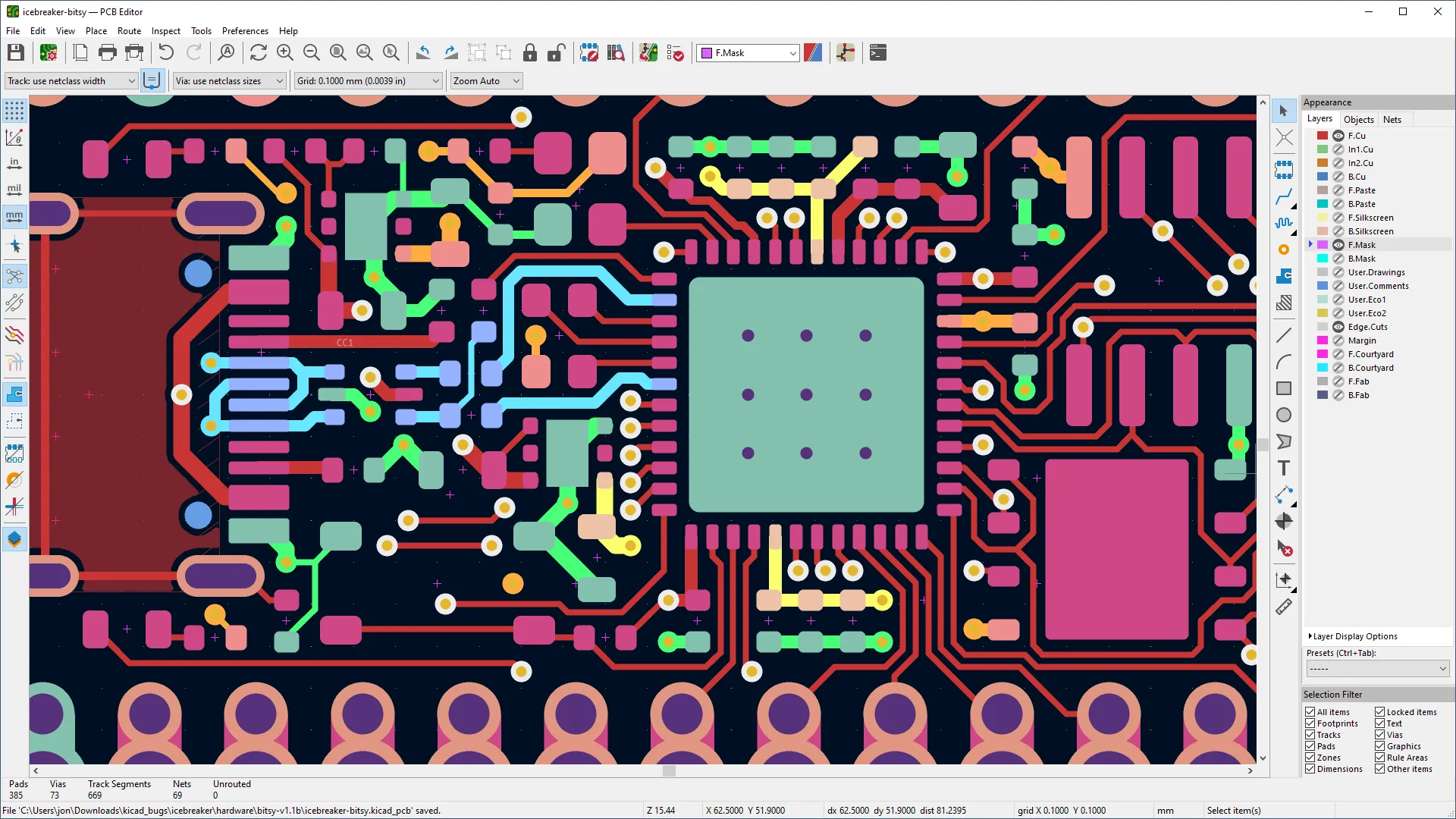
Step 3: Design the PCB Layout
The layout is where you arrange components on the board and route the traces (conductive paths) between them. For an easy PCB layout, follow these tips:
- Place larger components first, like ICs or connectors, then fit smaller ones around them.
- Keep traces short and direct to minimize signal delay. For a basic design operating at low frequencies (under 1 MHz), trace length isn’t usually a concern, but aim for efficiency.
- Separate power and ground traces to avoid interference. A common practice is to use a ground plane—a large area of copper connected to ground—to reduce noise.
Remember ASTM standards when choosing materials for your board. For instance, ensure your substrate (like FR-4) meets ASTM D709 criteria for heat resistance if your circuit will operate in warm conditions.
Step 4: Test and Validate Your Design
Before sending your design for manufacturing, use simulation tools in your software to test for errors. Check for short circuits, unconnected pins, or incorrect component values. Some software can even simulate signal integrity, ensuring that your traces won’t introduce unwanted delays or noise.
Refer to ASTM F1896 if you’re concerned about the conductivity of your traces. While you might not have the equipment to measure resistivity at home, understanding the standard helps you choose high-quality copper-clad boards for better performance.
Common Challenges in Simple Circuit Board Design
As a beginner, you’ll likely face a few hurdles in PCB design. Here’s how to tackle them while keeping ASTM standards in mind:
- Component Placement Issues: Crowding components can lead to heat buildup. Space them out evenly, ensuring there’s at least 0.1 inches between larger parts for airflow.
- Trace Routing Errors: Crossing traces or creating sharp angles can cause signal interference. Keep angles at 45 degrees or smoother curves for better signal flow, especially for designs with frequencies above 10 MHz.
- Material Selection: Using low-quality materials can lead to board failure. Stick to substrates and coatings that align with ASTM guidelines, like those specified in ASTM D709 or B545, for durability and solderability.
By anticipating these issues and planning ahead, you can create a reliable and efficient PCB even on your first try.
Tips for Circuit Design for Hobbyists
If you’re a hobbyist looking to dive into PCB design, here are some additional pointers to make the process smoother:
- Start Small: Begin with a basic project, like a single-LED circuit, before moving to complex designs. This builds confidence and helps you learn the software.
- Use Modular Designs: Break your circuit into smaller sections or modules. For example, design a power supply section separately from a control section to simplify troubleshooting.
- Leverage Online Resources: Many forums and tutorials offer free advice on PCB design. Look for communities where hobbyists share tips on easy PCB layout techniques.
- Double-Check Standards: Even for small projects, ensure your materials and processes loosely align with ASTM standards. This practice prepares you for more advanced designs later.
Why Following ASTM Standards Matters for Beginners
You might wonder why standards like ASTM are relevant for hobby projects or simple circuit board designs. The truth is, these guidelines aren’t just for professionals—they benefit everyone. Here’s why:
- Reliability: Standards ensure that your PCB won’t fail unexpectedly due to poor materials or construction. For instance, using a substrate that meets ASTM D709 ensures it can handle typical operating temperatures without warping.
- Safety: Proper soldering and coating, as outlined in ASTM B545, prevent issues like short circuits or corrosion, reducing the risk of fire or damage.
- Scalability: If you ever decide to turn your hobby into a product, designs that follow standards are easier to manufacture and certify for commercial use.
By incorporating these standards from the start, you build good habits that pay off as your skills grow.
Tools and Software for Easy PCB Layout
Modern PCB design software makes creating layouts accessible even for beginners. Many tools are free or low-cost, offering features like schematic capture, layout design, and simulation. Here are a few types of tools to consider:
- Free Software: Look for open-source options that provide basic design capabilities. They often include libraries of common components, saving you time.
- Simulation Features: Some programs let you test your circuit virtually, checking for issues like voltage drops or signal delays before you build.
- Community Support: Choose software with active user communities. If you’re stuck on a layout problem, other users can often help with advice or templates.
Start with a tool that matches your skill level, and don’t hesitate to experiment with different features as you learn. Most software includes tutorials or guides to help with your first simple circuit board design.
Conclusion: Building Confidence in PCB Design
PCB design for beginners doesn’t have to be overwhelming. By starting with the basics of easy PCB layout, following a clear PCB design tutorial, and understanding essential ASTM standards, you can create reliable and functional circuit boards. Whether you’re a hobbyist working on small projects or an aspiring engineer, these skills form the foundation for more complex designs in the future.
Remember to take it one step at a time. Define your circuit’s purpose, create a clean schematic, design a practical layout, and always validate your work. Incorporate ASTM standards like B545, D709, and F1896 to ensure quality, even in simple projects. With practice, you’ll gain the confidence to tackle any circuit design challenge that comes your way.
At ALLPCB, we’re committed to supporting your journey in circuit design for hobbyists and beyond. Use this guide as your starting point, and keep experimenting to refine your skills. Your next great project is just a design away!


