ALLPCB


When considering circuit board options for your next project, rigid flex PCBs often come up as a versatile solution due to their ability to combine the stability of rigid boards with the adaptability of flexible circuits. However, despite their many benefits, rigid flex PCBs may not always be the ideal choice for every application. If you're dealing with challenges like bulky connectors, the need for a robust material combination, or environments with high shock and vibration, there are critical limitations to consider. In this blog, we’ll dive deep into why rigid flex PCBs might not suit your needs and explore alternative solutions to ensure your design performs optimally.
What Are Rigid Flex PCBs? A Quick Overview
Rigid flex PCBs are hybrid circuit boards that integrate rigid and flexible sections into a single unit. The rigid parts provide structural support for components, while the flexible sections allow the board to bend or fold, making them ideal for compact or dynamic designs. They are widely used in industries like aerospace, medical devices, and consumer electronics where space-saving and reliability are key.
However, while they excel in certain scenarios, rigid flex PCBs come with drawbacks that can impact performance in specific applications. Let’s explore these limitations in detail, focusing on issues related to bulky connectors, robust material combinations, and handling shock and vibration.
Challenge 1: Compatibility with Bulky Connectors
One of the primary challenges with rigid flex PCBs is their compatibility with bulky connectors. These connectors, often required in applications needing high power or multiple signal lines, can pose significant design and assembly issues when paired with the delicate nature of flex sections.
In many designs, bulky connectors need to be mounted on the rigid portion of the PCB for stability. However, the transition areas between rigid and flexible sections are prone to stress, and attaching a heavy or large connector can exacerbate this. For instance, a connector weighing over 50 grams can create mechanical strain at the junction, potentially leading to cracking or delamination over time. This is especially problematic in applications where the board must endure repeated movement or bending.
Moreover, the flexible sections of these PCBs are often too thin or fragile to support the physical size and weight of larger connectors. This can limit your options for connector types, forcing you to either compromise on the connector’s capabilities or redesign the entire board layout. In high-density applications, where space is already constrained, this limitation can be a significant hurdle.
If your project relies on bulky connectors for power delivery or data transfer, a fully rigid PCB might be a better choice. Rigid boards provide a stable platform for heavy components without the risk of stress at flex points. Alternatively, using separate rigid and flexible boards connected via cables can offer a workaround, though this may increase assembly complexity.
Challenge 2: Limitations in Robust Material Combination
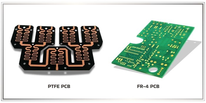
Another area where rigid flex PCBs may fall short is in achieving a robust material combination that meets the demands of harsh environments or specific performance criteria. The materials used in rigid flex designs, such as polyimide for flex sections and FR-4 for rigid areas, are chosen for their flexibility and stability. However, these materials may not always provide the durability or thermal resistance needed for certain applications.
For example, in high-temperature environments where components may operate above 150°C, the adhesive layers bonding the rigid and flexible sections can degrade, leading to delamination. Studies have shown that standard rigid flex materials can experience a 20% reduction in bond strength after prolonged exposure to temperatures above 120°C. This compromises the board’s structural integrity, making it unsuitable for applications like automotive engine control units or industrial machinery.
Additionally, when a robust material combination is required for chemical resistance or extreme mechanical durability, rigid flex PCBs often lack customization options. Unlike fully rigid boards, where you can select specialized laminates or coatings to withstand harsh conditions, the hybrid nature of rigid flex designs limits material choices. The flexible sections, in particular, are constrained to thinner, less durable materials to maintain bendability, which can be a weak point in demanding settings.
For projects needing a robust material combination, consider opting for rigid PCBs with enhanced laminates or coatings tailored to your environment. If flexibility is still required, a modular approach with separate rigid and flexible circuits might offer the durability you need without sacrificing performance.

Challenge 3: Performance in Shock and Vibration Environments
Rigid flex PCBs are often praised for their ability to reduce the number of connectors and cables, which can improve reliability in dynamic applications. However, when it comes to environments with high shock and vibration, their performance can be a concern. This is especially relevant for industries like aerospace, automotive, and military, where components are subjected to intense mechanical stress.
The flexible sections of these PCBs, while designed to bend, are not inherently resistant to continuous vibration. Over time, vibrations at frequencies above 100 Hz can cause fatigue in the copper traces within the flex areas, leading to microcracks or complete failures. Research indicates that rigid flex PCBs can experience a failure rate of up to 15% higher than rigid boards in vibration tests simulating automotive conditions (e.g., 5G acceleration over 1000 cycles).
Shock events, such as sudden impacts, pose an even greater risk. A drop test from a height of just 1 meter can induce stresses exceeding 2000 psi at the rigid-flex transition zones, potentially causing separation or damage. While rigid flex PCBs can be engineered with additional stiffeners or damping materials to mitigate these effects, this often increases cost and complexity, negating some of their space-saving advantages.
For applications exposed to high shock and vibration, fully rigid PCBs with proper mounting and damping mechanisms may offer better reliability. If flexibility is essential, consider using flexible circuits as separate components, reinforced with protective enclosures to absorb mechanical stress. These alternatives can provide the durability needed without the inherent vulnerabilities of a rigid flex design.

Other Drawbacks of Rigid Flex PCBs to Consider
Beyond the specific challenges of bulky connectors, robust material combinations, and shock and vibration, there are other general limitations to rigid flex PCBs that might influence your decision:
- Higher Manufacturing Costs: Rigid flex PCBs are more complex to design and fabricate than standard rigid or flexible boards. The process involves multiple layers, precise alignment, and specialized materials, often resulting in costs that are 30-50% higher per unit.
- Design Complexity: Designing a rigid flex PCB requires careful planning of bend radii, layer transitions, and component placement. Errors in design can lead to signal integrity issues, with impedance mismatches potentially causing signal delays of up to 10% in high-speed applications.
- Limited Repairability: If a rigid flex PCB fails, repairing it is often impractical due to the integrated nature of the rigid and flexible sections. Replacement costs can be significant, especially for custom designs.
These factors add to the reasons why rigid flex PCBs might not be the best fit for every project. Weighing these drawbacks against your application’s requirements is crucial before committing to this technology.
Alternatives to Rigid Flex PCBs
If rigid flex PCBs don’t meet your needs due to issues with bulky connectors, material durability, or shock and vibration, consider these alternative approaches:
- Fully Rigid PCBs: For applications requiring stability and support for heavy components, a fully rigid board offers unmatched reliability. They can handle larger connectors and are available in a wide range of materials for harsh environments.
- Separate Rigid and Flexible Circuits: Using distinct rigid and flexible boards connected via cables or small connectors allows you to tailor each section to specific needs. This modular approach can enhance durability in high-stress conditions.
- Hybrid Assemblies with Reinforcement: If some flexibility is needed, hybrid assemblies with reinforced flexible sections or external damping can provide a balance between adaptability and strength, especially in vibration-heavy settings.
Each of these alternatives has its own trade-offs in terms of cost, assembly time, and design effort, but they may better address the specific challenges of your project.
How to Decide If Rigid Flex PCBs Are Right for You
Choosing the right PCB type for your application involves a careful evaluation of your project’s requirements. Here are key considerations to guide your decision:
- Connector Size and Weight: If your design includes bulky connectors, assess whether the rigid sections can support them without stressing the flex areas.
- Environmental Conditions: Evaluate the operating temperature, chemical exposure, and mechanical stress your board will face. Ensure the materials used in a rigid flex design can withstand these conditions.
- Shock and Vibration Levels: For high-vibration environments, test or simulate the performance of a rigid flex PCB under expected conditions to identify potential failure points.
- Budget and Timeline: Factor in the higher costs and longer design cycles associated with rigid flex PCBs. Determine if the benefits justify the investment.
By analyzing these aspects, you can make an informed choice about whether rigid flex PCBs align with your project goals or if an alternative solution is more suitable.
Conclusion: Weighing the Pros and Cons
Rigid flex PCBs offer a unique combination of flexibility and stability, making them a powerful option for many modern electronics. However, they are not a one-size-fits-all solution. Challenges like compatibility with bulky connectors, limitations in achieving a robust material combination, and vulnerabilities in high shock and vibration environments can make them less ideal for certain applications.
Understanding these drawbacks allows you to make a smarter decision for your design. Whether you opt for a fully rigid board, a modular approach, or stick with rigid flex with additional reinforcements, the key is to prioritize the specific needs of your project. At ALLPCB, we’re committed to helping you navigate these choices with expert guidance and high-quality manufacturing solutions tailored to your requirements.