ALLPCB


Introduction
In modern electronics, power densities continue to rise, placing greater demands on printed circuit boards (PCBs) to manage heat effectively. Poor thermal management leads to elevated junction temperatures, accelerated component degradation, and reduced system reliability. Selecting the right PCB material with appropriate thermal conductivity becomes central to addressing these challenges. Engineers must balance thermal performance against electrical, mechanical, and cost constraints during the design phase. This article explores PCB material thermal conductivity as a foundational element in thermal management strategies. By understanding material options, designers can optimize heat dissipation and ensure long-term board performance.
Why Thermal Management Matters in PCBs
Thermal management directly impacts PCB reliability and operational lifespan. Excessive heat causes electromigration, delamination, and solder joint failures, compromising circuit integrity. In high-power applications like power supplies and LED lighting, inadequate heat spreading results in hotspots that exceed component ratings. Industry standards such as IPC-2221 provide guidelines for thermal design, emphasizing material selection to maintain safe operating temperatures. Effective thermal control also enhances signal integrity by minimizing temperature-induced variations in dielectric properties. Ultimately, prioritizing PCB material thermal conductivity prevents field failures and supports compliance with performance specifications.
Engineers face increasing pressure from miniaturization trends, where component density amplifies heat generation. Without proper materials, convective and radiative cooling alone prove insufficient for through-plane heat transfer. Material choices influence the overall thermal resistance network, from die to ambient. This underscores the need for high thermal conductivity PCB substrates in demanding environments. Selecting materials early in the design cycle avoids costly redesigns and iterations.
Understanding Thermal Conductivity in PCB Materials
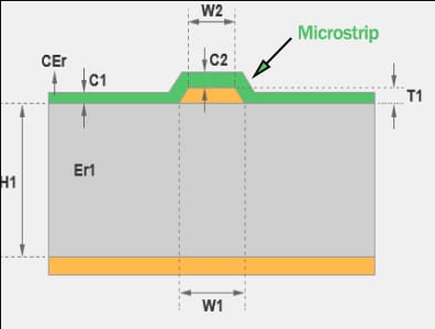
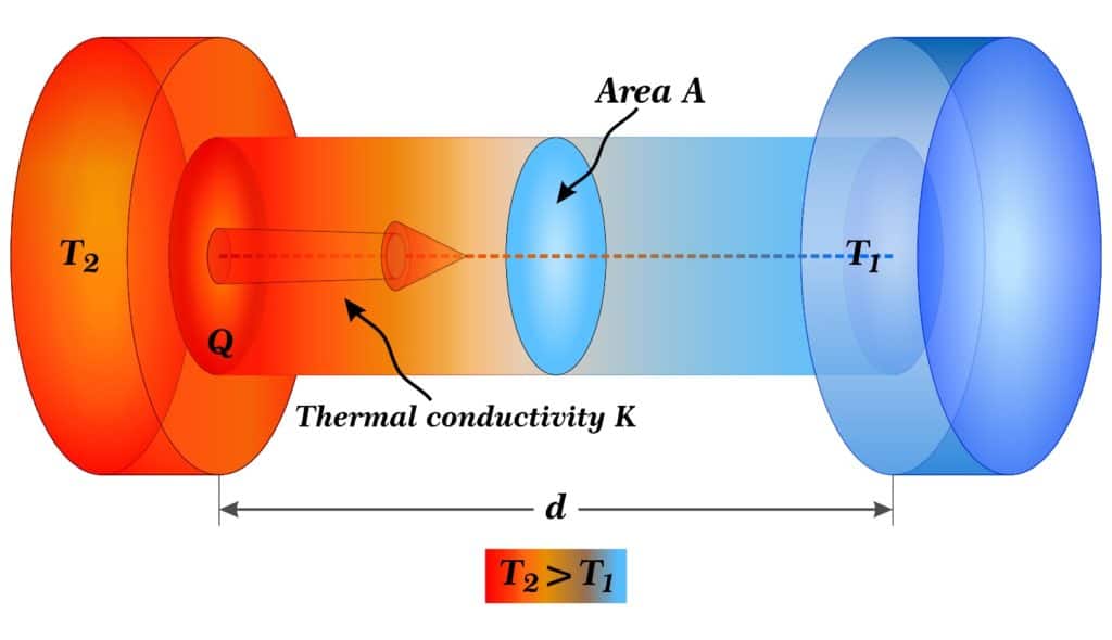
Thermal conductivity, denoted as k, measures a material's ability to conduct heat, typically in W/m·K. In PCBs, it varies significantly between in-plane (x-y) and through-plane (z-axis) directions due to laminate construction. Standard epoxy-based materials exhibit anisotropic behavior, with higher in-plane conductivity from copper planes. However, z-axis conductivity governs vertical heat flow from components to the board. Engineers must consider both when evaluating PCB material thermal conductivity for multilayer stacks.
Heat transfer mechanisms in PCBs include conduction through the substrate, vias, and planes, supplemented by convection and radiation. Low-k materials impede conduction, forcing reliance on secondary paths like thermal vias. High thermal conductivity PCB designs leverage substrates that enhance direct heat spreading. Factors such as filler content and reinforcement type dictate these properties. Accurate modeling requires datasheet values aligned with application needs.
Common PCB Materials and Their Thermal Properties
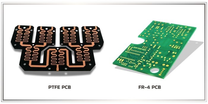
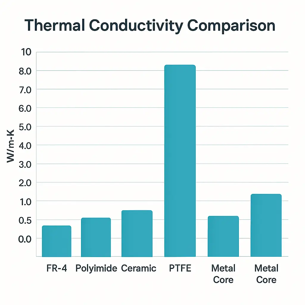
FR4 remains the baseline for most PCBs, offering cost-effective insulation with moderate thermal performance. Its fiberglass-reinforced epoxy provides mechanical stability but limited heat dissipation, suitable for low-to-medium power designs. In comparisons like FR4 vs aluminum, FR4 falls short in high-heat scenarios due to its lower inherent conductivity. Designers often compensate with copper pours and vias, yet this approach has limits in dense layouts.
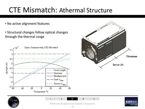
Metal core PCBs, particularly aluminum-based, excel in applications requiring superior heat sinking. The metallic core acts as an integrated heat spreader, channeling heat to external dissipators efficiently. This makes metal core PCB ideal for power electronics where through-plane conductivity is paramount. Compared to FR4, aluminum substrates reduce thermal resistance significantly, though they demand careful CTE matching to prevent warping. Electrical isolation layers ensure functionality without shorts.
Ceramic PCBs represent an advanced option for extreme thermal demands. Their inorganic composition delivers high thermal conductivity while maintaining excellent electrical insulation. Ceramic PCB suits high-frequency and high-power RF modules, resisting thermal shock better than organics. Drawbacks include higher cost and brittleness, necessitating precise handling in fabrication.
Rogers materials, known for their specialized formulations, bridge high-frequency needs with enhanced thermal properties. Ceramic-filled composites in these laminates improve conductivity over standard FR4 without sacrificing low loss. High thermal conductivity PCB using such materials supports demanding aerospace and telecom applications. Selection depends on balancing dielectric constant, loss tangent, and thermal needs.
Related Reading: The Ultimate Guide to PCB Thermal Management: Techniques, Materials, and Design
FR4 vs Aluminum: A Direct Comparison
FR4 vs aluminum highlights trade-offs in thermal management. FR4's organic resin limits z-axis heat flow, making it prone to hotspots under load. Aluminum cores, by contrast, provide a direct conduction path, lowering peak temperatures across the board. This difference proves critical in LED drivers or motor controls, where sustained power generates substantial heat.
Mechanically, aluminum offers rigidity but expands differently than copper traces, risking stress during thermal cycling. FR4 matches copper CTE more closely, aiding reliability in standard assemblies. Cost-wise, FR4 enables high-volume production, while aluminum suits specialized runs. Electrical performance favors FR4 for signal integrity, as metal cores may introduce parasitics.
In practice, hybrid approaches combine FR4 multilayers on aluminum bases for optimized performance. This leverages FR4's routing flexibility with aluminum's dissipation. Standards like IPC-4101 classify base materials by thermal grades, guiding such selections. Engineers simulate both to predict junction temperatures accurately.
Related Reading: Copper vs. Aluminum MCPCB: Choosing the Right Metal Core for Your PCB
Factors Influencing PCB Material Selection for Thermal Management
Beyond conductivity, electrical properties like dielectric constant affect high-speed signals. High thermal conductivity PCB materials often feature lower Dk for RF compatibility. Mechanical factors, including CTE and modulus, prevent failures from thermal expansion mismatch. Cost and availability influence scalability, with FR4 dominating volume production.
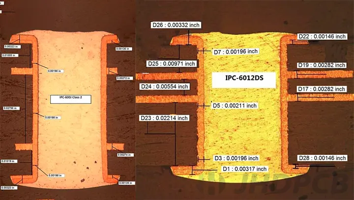
Environmental exposure demands consideration of moisture absorption and Tg. High Tg variants enhance stability under reflow. Fabrication compatibility, per IPC-6012 qualification, ensures yield. Application specifics, such as operating frequency and power level, dictate ceramic or metal core over FR4.
Testing validates choices using JEDEC JESD51-7 for high effective thermal conductivity boards. This standardizes thermal test environments, enabling comparable results. Simulation tools model material stacks pre-prototype.
Best Practices for Selecting and Implementing High Thermal Conductivity PCBs
Start with power budget analysis to identify heat sources. Map thermal paths and calculate required k values qualitatively. Consult IPC-2221 for layout aids like thermal reliefs and plane sizing. Prioritize thick copper for in-plane spreading, augmented by filled vias.
Layer stacking optimizes heat flow; place power planes near cores in metal core PCB. Integrate embedded heat pipes or graphite sheets for ultra-high demands. Prototype testing under load confirms predictions. Collaborate with fabricators early for material availability.
For ceramic PCB, ensure process controls match fragility. Rogers material integration requires precise lamination parameters. Monitor warpage post-assembly.
Case Study: Power Converter Design
In a high-power DC-DC converter, initial FR4 prototypes showed junction temperatures exceeding limits. Switching to aluminum metal core PCB reduced hotspots by enhancing base dissipation. Ceramic elements handled RF sections, maintaining efficiency. Final design met IPC-2221 thermal guidelines, extending MTBF significantly. This case illustrates material selection's role in balancing performance and reliability.
Conclusion
PCB material selection drives effective thermal management, directly influencing reliability and efficiency. From FR4's versatility to metal core PCB and ceramic options, each offers unique advantages. High thermal conductivity PCB solutions like aluminum substrates and advanced laminates address rising power demands. Adhering to standards such as IPC-4101 and JEDEC JESD51-7 ensures robust designs. Engineers should integrate thermal analysis early, weighing trade-offs holistically. Prioritizing PCB material thermal conductivity yields cooler, longer-lasting electronics.
FAQs
Q1: What is PCB material thermal conductivity, and why does it matter for electric engineers?
A1: PCB material thermal conductivity refers to the substrate's ability to transfer heat, critical for managing hotspots in power-dense designs. Low conductivity in FR4 limits vertical heat flow, risking component failure. High thermal conductivity PCB materials like ceramic or metal core improve dissipation, aligning with IPC-2221 guidelines. Engineers use it to predict temperatures, ensuring compliance and reliability in applications like power electronics.
Q2: How does FR4 vs aluminum compare in thermal performance?
A2: FR4 provides adequate performance for low-power boards but struggles with high heat loads due to poor z-axis conductivity. Aluminum metal core PCB excels in spreading heat to chassis, ideal for LEDs and drivers. FR4 costs less and suits signals better, while aluminum demands CTE management. Selection hinges on power levels and cost, per material classifications in IPC-4101.
Q3: When should I choose a ceramic PCB for thermal management?
A3: Opt for ceramic PCB in high-power RF or harsh environments needing superior insulation and conductivity. It outperforms FR4 in thermal shock resistance, suiting aerospace uses. Brittleness requires careful fabrication and handling, but the benefits justify it for extreme cases. JEDEC standards aid testing high thermal conductivity PCB like ceramics.
Q4: Are Rogers materials suitable for high thermal conductivity PCBs?
A4: Rogers materials, with ceramic fillers, offer enhanced thermal conductivity alongside low-loss dielectrics for high-frequency needs. They bridge FR4 limitations in demanding telecom designs. Balance them with cost and electrical specifications during selection. Standards like IPC-2221 guide integration for optimal thermal paths.
References
IPC-2221B - Generic Standard on Printed Board Design. IPC, 2003
IPC-4101E - Specification for Base Materials for Rigid and Multilayer Printed Boards. IPC, 2010
JEDEC JESD51-7 - High Effective Thermal Conductivity Test Board for Leaded Surface Mount Packages. JEDEC, 2004