 ALLPCB


When designing printed circuit boards (PCBs) for LED applications, achieving uniform lighting is a top priority. Whether you're working on a display, backlighting, or ambient lighting project, the placement of LEDs plays a critical role in ensuring consistent light output and minimizing shadows. So, how do you optimize LED placement for uniform illumination on PCBs? The key lies in strategic spacing, thoughtful layout design, and understanding the light distribution properties of your LEDs. In this comprehensive guide, we'll dive into LED placement strategies for uniform illumination, calculating LED spacing on PCBs, minimizing shadows on LED boards, designing for consistent light output, and LED PCB layout guidelines to help you create efficient and effective designs.
Why Uniform Lighting Matters in LED PCB Design
Uniform lighting is essential for both aesthetic and functional reasons. Uneven light distribution can create hotspots or dark areas, which can ruin the visual appeal of a product or reduce its effectiveness in applications like backlighting for displays. Poor LED placement can also lead to inefficiencies, such as wasted energy or the need for additional components to correct lighting issues. By optimizing LED placement, you ensure better performance, lower costs, and a more professional end result.
Key Factors Affecting Uniform Illumination on PCBs
Before diving into specific strategies, it's important to understand the factors that influence light uniformity on a PCB. These include:
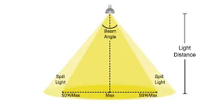
- LED Beam Angle: The angle at which an LED emits light determines how much area it covers. Narrow beam angles may create focused light with potential dark spots, while wider angles can overlap and cause hotspots if not spaced correctly.
- LED Intensity: Variations in LED brightness or power can lead to inconsistent lighting if not accounted for in the design.
- PCB Surface and Material: Reflective or absorptive surfaces can affect how light spreads across the board.
- Spacing and Layout: The distance between LEDs and their arrangement on the PCB directly impacts light distribution.
- Thermal Management: Overheating can reduce LED performance, leading to uneven light output over time.
With these factors in mind, let's explore actionable strategies for optimizing LED placement.
LED Placement Strategies for Uniform Illumination
Achieving uniform illumination starts with a well-thought-out placement strategy. Here are some proven approaches to consider when designing your PCB layout:
1. Use a Grid or Symmetrical Pattern
Placing LEDs in a grid or symmetrical pattern is one of the simplest ways to ensure even light distribution. This approach works well for applications like panel lighting or backlighting. By maintaining equal spacing in both horizontal and vertical directions, you reduce the chances of dark spots or overly bright areas. For example, a 4x4 grid of LEDs on a square PCB can provide balanced coverage if the spacing is calculated based on the beam angle and desired light overlap.
2. Account for Edge Effects
Edges of a PCB often receive less light because there are fewer LEDs contributing to illumination in those areas. To counter this, consider placing LEDs closer together near the edges or using higher-intensity LEDs in those spots. Another option is to add reflective materials around the perimeter to bounce light back into the weaker areas.
3. Optimize for Specific Applications
Different projects have different lighting needs. For instance, a display backlight might require a denser LED arrangement to avoid visible shadows, while an indicator light panel might need fewer LEDs with wider spacing. Tailor your placement strategy to the specific requirements of your application for the best results.
Calculating LED Spacing on PCBs
One of the most critical steps in achieving uniform lighting is determining the correct spacing between LEDs. Proper spacing prevents overlap (which causes hotspots) and gaps (which create shadows). Here's how to calculate it:
Step 1: Determine the LED Beam Angle
LEDs come with a specified beam angle, often ranging from 60 to 120 degrees for standard surface-mount LEDs. This angle indicates the spread of light from the center of the LED. Check the datasheet of your chosen LED for this value.
Step 2: Calculate the Coverage Area
The coverage area depends on the beam angle and the distance between the LED and the surface it illuminates (if applicable). For a PCB where LEDs are close to the surface, you can use a simple formula based on trigonometry:
Coverage Diameter = 2 * Distance * tan(Beam Angle / 2)
For example, if your beam angle is 120 degrees and the distance to the illuminated surface is 10 mm, the coverage diameter is approximately 34.6 mm. This means each LED covers a circular area with a diameter of 34.6 mm.
Step 3: Set Spacing for Overlap
To avoid dark spots, ensure the coverage areas of adjacent LEDs overlap slightly. A common practice is to space LEDs at about 70-80% of the coverage diameter. Using the previous example, spacing LEDs at 24-28 mm apart would provide a small overlap, ensuring uniform light distribution.
Step 4: Adjust Based on Testing
After calculating theoretical spacing, build a prototype and test the light output. Use a light meter to measure illuminance across the surface and adjust spacing if you notice uneven areas. Fine-tuning is often necessary to account for real-world factors like lens effects or PCB material properties.
Minimizing Shadows on LED Boards
Shadows can disrupt the uniformity of lighting and are often caused by obstructions, poor spacing, or uneven LED placement. Here are some tips to minimize shadows on your LED boards:
- Avoid Obstructing Components: Keep tall components, like capacitors or connectors, away from the direct path of LED light. Place them on the opposite side of the PCB if possible.
- Use Diffusers: Adding a light diffuser layer above the LEDs can help scatter light more evenly, reducing the appearance of shadows caused by individual LED points.
- Staggered Layouts: In some cases, a staggered or hexagonal layout can reduce shadow effects compared to a strict grid, as it minimizes direct alignment of LEDs and potential dark spots.
- Increase LED Density: If shadows persist, consider adding more LEDs at closer intervals to fill in gaps, though this must be balanced with power and heat considerations.
Designing for Consistent Light Output
Consistency in light output goes beyond placement—it involves electrical and thermal design as well. Here are key considerations to ensure your LEDs perform uniformly over time:
1. Match LED Specifications
Use LEDs from the same batch or with closely matched specifications for brightness (measured in lumens) and color temperature. Variations in these parameters can lead to visible differences in light output, even with perfect placement.
2. Ensure Proper Current Distribution
LEDs require consistent current to maintain uniform brightness. Design your PCB traces to minimize voltage drops across the board. For a typical 3.2V LED operating at 20 mA, a voltage drop of just 0.1V due to trace resistance can noticeably dim the LED. Use wider traces or a star topology for power distribution to avoid this issue.
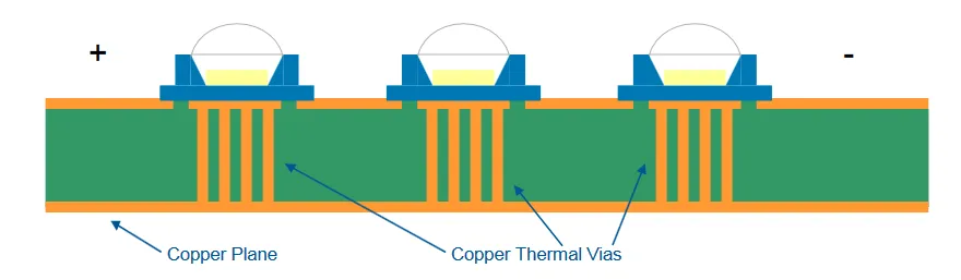
3. Manage Heat Effectively
Heat buildup can degrade LED performance, causing some areas of the board to appear dimmer. Incorporate thermal vias and heat sinks into your PCB design to dissipate heat evenly. For high-power LEDs (e.g., 1W or more), ensure the PCB substrate has good thermal conductivity, such as aluminum-based materials with a thermal conductivity of around 1-2 W/m·K.
LED PCB Layout Guidelines
Finally, follow these general LED PCB layout guidelines to tie together all aspects of your design for optimal performance:
- Plan Power Traces First: Route power traces to ensure equal current delivery to all LEDs. Avoid long, thin traces that could introduce resistance and voltage drops.
- Minimize Trace Lengths: Keep signal and power traces as short as possible to reduce interference and power loss, especially in high-density LED designs.
- Group LEDs Logically: If your design includes multiple LED zones (e.g., for dimming or color control), group them in a way that simplifies wiring and control circuitry while maintaining uniform spacing.
- Consider Assembly Constraints: Ensure your LED placement aligns with pick-and-place machine capabilities during manufacturing. For instance, maintain a minimum clearance of 0.5 mm between components for accurate placement.
- Test Iteratively: Build and test prototypes at different stages of design to catch lighting or electrical issues early. Use simulation tools to predict light distribution before finalizing the layout.
Tools and Resources for LED PCB Design
Modern design software can help you visualize and optimize LED placement before manufacturing. Many tools offer simulation features to predict light distribution and thermal performance. Look for software with built-in libraries for LED components and customizable grid layouts to streamline the design process. Additionally, consult LED manufacturer datasheets for detailed specifications on beam angles, power requirements, and recommended spacing.
Conclusion
Optimizing LED placement for uniform lighting on PCBs is a blend of science and art. By following LED placement strategies for uniform illumination, mastering calculating LED spacing on PCBs, focusing on minimizing shadows on LED boards, prioritizing designing for consistent light output, and adhering to LED PCB layout guidelines, you can create designs that deliver exceptional performance. Whether you're illuminating a small display or a large panel, careful planning and testing will ensure your LEDs shine evenly and efficiently. With the tips and techniques outlined in this guide, you're well-equipped to tackle your next LED PCB project with confidence.


