ALLPCB


Green solder mask is a common yet critical component of printed circuit boards (PCBs), protecting copper traces and preventing solder bridges during assembly. However, issues like cracks, peeling, or misalignment can compromise PCB functionality. If you're facing challenges with green solder mask troubleshooting, PCB repair, or PCB rework, this guide offers practical solutions. From visual inspection tips to addressing solder mask defects, we’ll walk you through actionable steps to ensure your boards perform reliably.
In this comprehensive blog, we dive deep into the world of green solder mask troubleshooting. Whether you're an electronics engineer or a hobbyist working on PCB repair, you'll find detailed techniques, visual inspection strategies, and solutions for common solder mask defects. Let’s get started with everything you need to know to maintain the integrity of your PCBs.
What Is Green Solder Mask and Why Does It Matter?
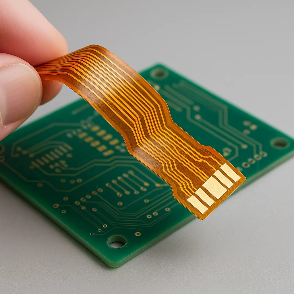
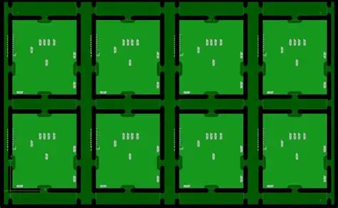
The green solder mask is a thin polymer layer applied to the surface of a PCB. Its primary role is to protect the copper traces from oxidation, environmental damage, and unintended solder connections during assembly. The green color, while not functionally significant, has become an industry standard due to its visibility and contrast against copper and components, making visual inspections easier.
Without a proper solder mask, your PCB is at risk of short circuits, corrosion, and mechanical damage. Issues with the solder mask—such as cracks, incomplete coverage, or adhesion problems—can lead to costly failures. For electronics engineers, understanding how to troubleshoot these issues is essential for maintaining high-quality boards, especially during PCB rework or repair tasks.

Common Solder Mask Defects and Their Causes
Before diving into troubleshooting techniques, it’s important to understand the common defects associated with green solder mask. Identifying the root cause of these issues can save time during PCB repair and rework. Here are some frequent problems:
- Cracks or Peeling: Often caused by thermal stress during soldering or improper curing of the mask during manufacturing. Cracks expose copper traces, increasing the risk of oxidation or short circuits.
- Incomplete Coverage: This occurs when the solder mask fails to cover certain areas, leaving copper vulnerable. It can result from poor application techniques or contamination on the board surface.
- Misalignment: If the solder mask layer isn’t aligned properly with the PCB layout, it can expose pads or traces meant to be protected, leading to soldering errors.
- Blistering or Delamination: Excessive moisture or heat during manufacturing can cause the mask to bubble or separate from the board, compromising its protective function.
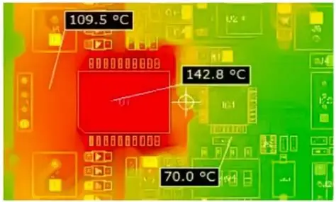
- Discoloration: While not always a functional issue, discoloration can indicate exposure to excessive heat or chemical contamination, potentially weakening the mask over time.
Understanding these defects is the first step in effective green solder mask troubleshooting. By pinpointing the cause, you can apply the right solution during PCB repair or rework processes.
Visual Inspection Tips for Identifying Solder Mask Issues
Visual inspection is a critical skill for electronics engineers working on PCB repair. Catching solder mask defects early can prevent major issues down the line. Here are practical tips to enhance your visual inspection process:
- Use Proper Lighting: Inspect the PCB under bright, uniform lighting. A magnifying lamp with at least 5x magnification can help spot tiny cracks or incomplete coverage in the green solder mask.
- Check for Uniformity: Look for inconsistencies in color or texture. A healthy solder mask should appear smooth and evenly applied. Discoloration or rough patches may indicate a problem.
- Examine Edges and Corners: Defects like peeling or cracks often start at the edges of the board or near high-stress areas like mounting holes. Pay close attention to these spots.
- Inspect Around Pads and Vias: Ensure the solder mask properly tents vias (if intended) and doesn’t encroach on solder pads. Misalignment here can lead to soldering issues during assembly or rework.
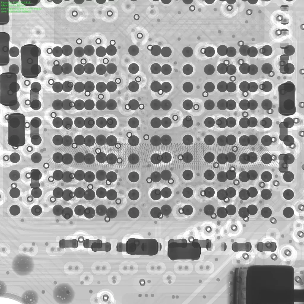
- Use a Microscope for Precision: For detailed inspection, a stereo microscope with 10x to 40x magnification can reveal micro-cracks or adhesion issues not visible to the naked eye.
Regular visual inspections during and after manufacturing can help catch solder mask defects before they escalate. Documenting any issues with photographs can also aid in troubleshooting and communication with manufacturing teams.

Green Solder Mask Troubleshooting Techniques
Once you’ve identified a solder mask defect through visual inspection, the next step is troubleshooting and repair. Below are proven techniques to address common issues with green solder mask during PCB repair and rework:
1. Repairing Cracks or Peeling
Cracks or peeling in the solder mask expose copper traces, risking corrosion or short circuits. To repair this:
- Clean the affected area with isopropyl alcohol (at least 90% concentration) and a soft brush to remove debris or contaminants.
- Apply a small amount of UV-curable solder mask repair material using a fine-tip applicator. Ensure the material matches the green color for consistency.
- Cure the repair material under a UV lamp (typically 365 nm wavelength) for 10-15 minutes, following the manufacturer’s guidelines.
- Inspect the repaired area to confirm full coverage and adhesion.
2. Addressing Incomplete Coverage
If certain areas lack solder mask coverage, you can use a touch-up method:
- Prepare the surface by cleaning it with alcohol to remove any residue.
- Apply a thin layer of liquid solder mask using a precision brush or pen applicator.
- Cure the mask as per the product instructions, ensuring it bonds properly to the board.
3. Fixing Misalignment Issues
Misaligned solder mask can be trickier to fix during PCB rework. If the misalignment exposes critical areas:
- Use a small amount of solder mask material to cover exposed copper manually.
- If the issue is widespread, consider consulting with your manufacturing partner to prevent similar errors in future batches.
4. Dealing with Blistering or Delamination
Blistering often results from trapped moisture or heat stress. While severe cases may require a full rework, minor issues can be managed:
- Gently sand the blistered area with fine-grit sandpaper (800-1000 grit) to remove loose material.
- Apply a new layer of solder mask and cure it properly to restore protection.
These troubleshooting techniques can extend the life of your PCB and prevent failures during operation. Always wear appropriate protective gear, such as gloves and safety glasses, when handling chemicals or UV equipment.

Preventing Solder Mask Defects in Future Designs
While troubleshooting and PCB repair are essential skills, preventing solder mask defects in the first place is even better. Here are design and manufacturing tips for electronics engineers to minimize issues with green solder mask:
- Optimize Design Clearances: Ensure your PCB layout includes proper clearances between pads and traces for solder mask application. A minimum clearance of 0.1 mm around pads can prevent overlap or incomplete coverage.
- Specify Via Tenting: Clearly indicate in your design files whether vias should be tented (covered by solder mask) or left open. Incomplete tenting can lead to exposed copper.
- Control Manufacturing Conditions: Work with your fabrication team to ensure proper curing temperatures (typically 120-150°C for 30-60 minutes) and humidity levels during solder mask application. Excessive moisture can cause blistering.
- Use Quality Materials: Opt for high-quality solder mask materials that withstand thermal and mechanical stress. Poor-quality masks are more prone to cracking or peeling.
- Perform Pre-Production Testing: Before full-scale production, test a prototype batch under real-world conditions to identify potential solder mask issues early.
By incorporating these practices into your workflow, you can reduce the need for extensive PCB rework and ensure long-term reliability.
Tools and Materials for Green Solder Mask Troubleshooting
Having the right tools on hand can make green solder mask troubleshooting and PCB repair much easier. Here’s a list of essentials for electronics engineers:
- Magnifying Lamp or Microscope: For detailed visual inspection of solder mask defects. A lamp with 5-10x magnification works well for most tasks.
- UV-Curable Solder Mask: Available in green to match standard PCBs. Look for products with a curing time of under 15 minutes for efficiency.
- Precision Applicators: Fine-tip brushes or pens for applying solder mask repair material accurately.
- Isopropyl Alcohol: At least 90% concentration for cleaning surfaces before repair.
- UV Lamp: A small handheld lamp with a 365 nm wavelength for curing repair material.
- Fine-Grit Sandpaper: Useful for smoothing blistered or delaminated areas before applying new mask material.
Investing in these tools ensures you’re prepared for any solder mask issue that arises during PCB repair or rework.
When to Seek Professional Help for PCB Rework
While many solder mask issues can be resolved with the techniques above, some scenarios require professional intervention. If you encounter the following, consider reaching out to a specialized PCB rework service:
- Widespread delamination or blistering across the board, indicating a manufacturing defect.
- Complex multilayer boards where solder mask repair risks damaging inner layers.
- Persistent issues despite multiple repair attempts, suggesting an underlying design flaw.
Professional services have access to advanced equipment and expertise, ensuring high-quality repairs without compromising the board’s functionality.
Conclusion: Mastering Green Solder Mask Troubleshooting
Troubleshooting green solder mask issues is a valuable skill for any electronics engineer working on PCB repair or rework. By mastering visual inspection techniques, applying targeted repair methods, and implementing preventative design practices, you can maintain the integrity of your boards and avoid costly failures. From identifying common solder mask defects like cracks and peeling to using the right tools for the job, this guide provides a practical roadmap for success.
Whether you’re dealing with a one-off repair or optimizing a production run, understanding how to handle green solder mask challenges ensures your PCBs perform reliably in any application. Keep these tips and techniques in mind, and you’ll be well-equipped to tackle any solder mask issue that comes your way.