ALLPCB


In today’s world, air quality monitoring has become a critical tool for ensuring healthier environments, especially in urban and industrial areas. With the rise of IoT (Internet of Things), integrating wireless communication like Wi-Fi and LoRa into air quality monitoring PCBs (Printed Circuit Boards) offers a powerful way to collect and transmit data in real time. This blog post dives deep into how to seamlessly incorporate Wi-Fi connectivity for air quality PCB and LoRa integration with sensors, while exploring key design aspects such as antenna placement on PCB, wireless data transmission, IoT air quality monitoring, and optimizing wireless range. Whether you're an engineer or a designer, this guide will provide actionable insights to enhance your next project.
Why Wireless Communication Matters for Air Quality Monitoring
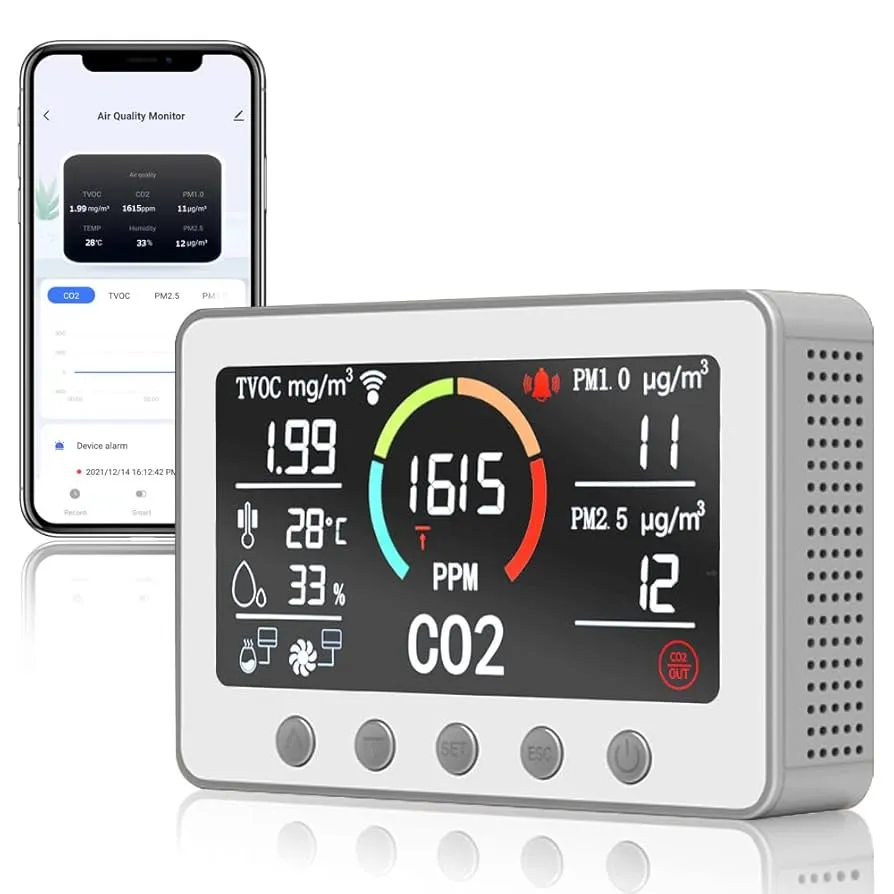
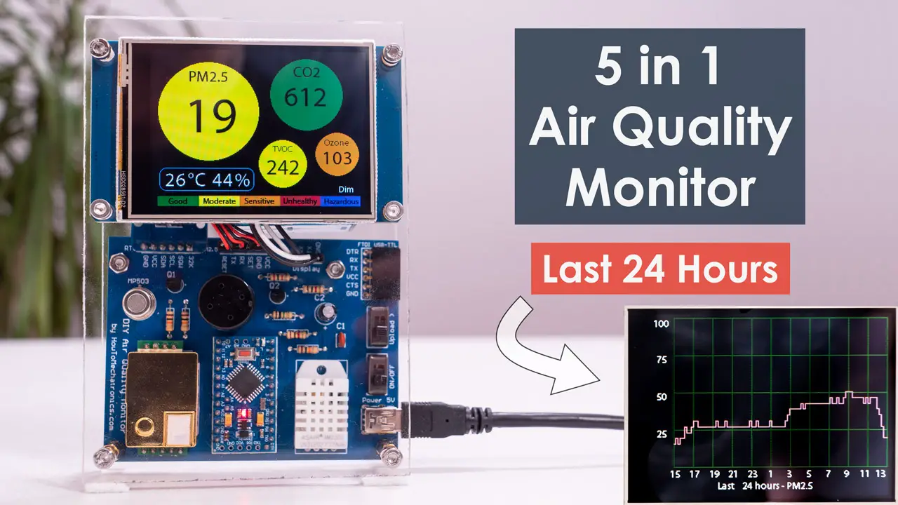
Air quality monitoring systems are essential for detecting pollutants like PM2.5, CO2, and volatile organic compounds (VOCs). Traditional wired systems can be costly and inflexible, especially for large-scale or remote deployments. Wireless communication, such as Wi-Fi and LoRa, solves these challenges by enabling real-time data transmission over short or long distances without the need for extensive cabling. Wi-Fi is ideal for indoor or urban settings with existing network infrastructure, while LoRa excels in rural or remote areas due to its long-range, low-power capabilities.
By embedding wireless technologies into PCBs, you can create compact, efficient, and scalable solutions for IoT air quality monitoring. This integration not only reduces installation costs but also allows for flexible sensor placement and easy data access via cloud platforms.
Understanding Wi-Fi Connectivity for Air Quality PCB Design
Wi-Fi is a popular choice for air quality monitoring in environments where internet infrastructure is readily available. It offers high data rates, making it suitable for transmitting detailed sensor data quickly. When designing a PCB with Wi-Fi connectivity for air quality PCB, consider the following:
- Module Selection: Choose a Wi-Fi module that supports common standards like 802.11n or 802.11ac for better speed and reliability. Many modules operate at 2.4 GHz, which provides a good balance of range and bandwidth, though 5 GHz can be used for faster data rates in closer proximity.
- Power Consumption: Wi-Fi modules can consume significant power, often around 100-300 mA during active transmission. Opt for low-power modes or duty cycling to extend battery life in portable devices.
- Integration: Ensure the module interfaces well with your microcontroller unit (MCU) via protocols like SPI or UART. Proper impedance matching (typically 50 ohms for RF lines) is crucial to minimize signal loss.
Wi-Fi is best suited for indoor or urban monitoring where devices are within 50-100 meters of a router or access point. However, interference from other devices on the same frequency band can affect performance, so plan for robust error handling in your firmware.
LoRa Integration with Sensors for Long-Range Monitoring
For applications requiring long-range communication, such as outdoor or rural air quality monitoring, LoRa integration with sensors is a game-changer. LoRa (Long Range) operates on sub-GHz frequencies (e.g., 868 MHz in Europe, 915 MHz in North America) and can transmit data over distances of 5-15 kilometers in open areas while consuming minimal power, often less than 20 mA during transmission.
Key considerations for integrating LoRa into your PCB design include:
- LoRa Module: Select a module that supports LoRaWAN, a protocol for wide-area networks, to connect multiple devices to a gateway. Bandwidth and spreading factor settings can be adjusted to balance range and data rate. For instance, a spreading factor of 12 offers maximum range but reduces data rate to about 300 bps.
- Sensor Compatibility: Pair LoRa with sensors like PM2.5 detectors or gas sensors (e.g., for CO or NO2). Ensure the MCU can process sensor data and format it for LoRa transmission.
- Power Efficiency: LoRa’s low power draw makes it ideal for battery-powered devices. Devices can operate for months or even years on a single battery by transmitting data only periodically (e.g., every 10 minutes).
LoRa shines in IoT air quality monitoring for large-scale deployments, such as city-wide pollution tracking or remote environmental studies, where traditional Wi-Fi networks are unavailable.
Antenna Placement on PCB: Best Practices for Signal Strength
Whether using Wi-Fi or LoRa, antenna placement on PCB is critical to ensure reliable wireless data transmission. A poorly placed antenna can lead to signal loss, reduced range, or interference. Follow these best practices:
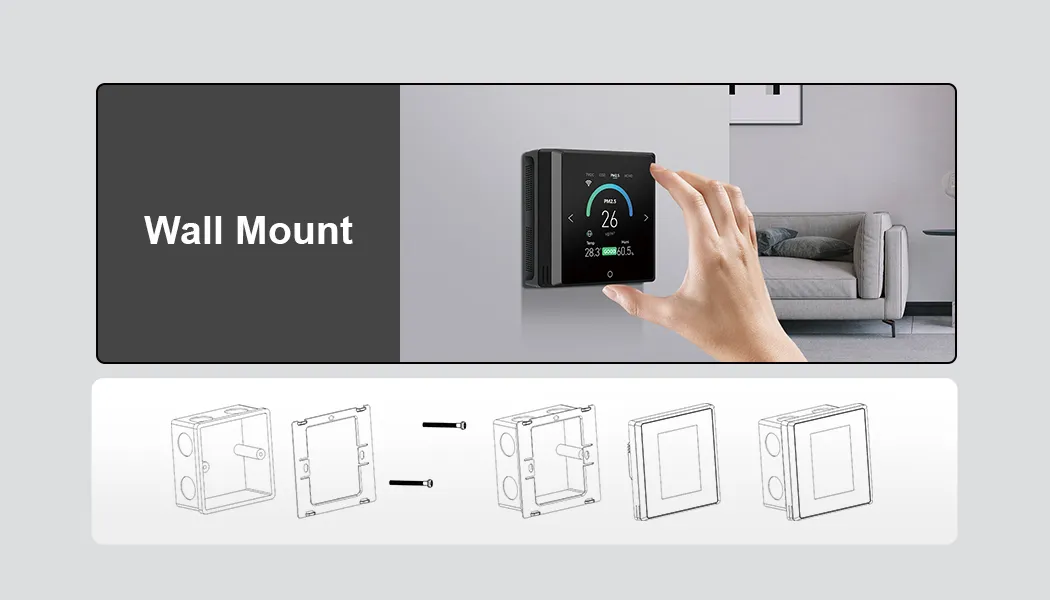
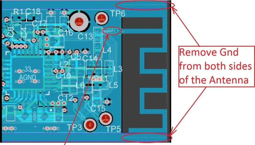
- Location: Place the antenna at the edge of the PCB, away from ground planes, power lines, and noisy components like switching regulators. For Wi-Fi, a clear line of sight to the router improves performance, while LoRa antennas benefit from elevation to maximize range.
- Type of Antenna: Use a trace antenna for compact designs or an external antenna (e.g., whip or helical) for better range. Ensure the antenna’s impedance matches the RF line (typically 50 ohms) to avoid signal reflection.
- Ground Plane: Design a proper ground plane beneath the antenna to improve radiation efficiency. For a quarter-wave antenna at 915 MHz (LoRa), the ground plane should ideally extend at least 82 mm in length.
- Testing: Use a network analyzer to measure the antenna’s return loss (S11 parameter). A value below -10 dB indicates good impedance matching and minimal signal loss.
Proper antenna design directly impacts optimizing wireless range. For example, a well-placed LoRa antenna can achieve a range of up to 10 km in rural areas, while Wi-Fi might be limited to 50 meters indoors if obstacles or interference are present.
Wireless Data Transmission: Ensuring Reliability and Efficiency
Wireless data transmission is the backbone of any IoT air quality monitoring system. Both Wi-Fi and LoRa have unique strengths and challenges when it comes to sending sensor data to a central server or cloud platform.
- Wi-Fi Data Transmission: Wi-Fi supports high data throughput, often up to 100 Mbps with modern standards. This allows for frequent updates and large data packets, which is useful for real-time dashboards. However, ensure encryption (e.g., WPA3) to secure data, especially if transmitting over public networks.
- LoRa Data Transmission: LoRa prioritizes range over speed, with data rates ranging from 0.3 to 50 kbps depending on the spreading factor. It’s best for sending small, periodic updates (e.g., air quality readings every 5 minutes). Use error correction techniques like forward error correction (FEC) to handle signal degradation over long distances.
- Protocol Choice: For Wi-Fi, MQTT or HTTP protocols work well for cloud integration. For LoRa, LoRaWAN provides a structured way to connect multiple devices to a gateway, which then forwards data to the cloud.
Reliability is key in air quality monitoring. Dropped data can mean missing critical pollution spikes. Test your system under real-world conditions to ensure consistent wireless data transmission, and consider redundancy (e.g., local storage on the device) in case of connectivity issues.
Optimizing Wireless Range for Maximum Coverage
Optimizing wireless range is essential to ensure your air quality monitoring system covers the intended area effectively. Here are actionable tips for both Wi-Fi and LoRa:
- Wi-Fi Range Optimization: Position devices closer to access points or use repeaters to extend coverage. Avoid physical barriers like walls or metal objects that can attenuate signals. A typical indoor range is 20-50 meters, but this can drop to 10 meters with interference.
- LoRa Range Optimization: Elevate devices or gateways to reduce obstructions. In urban areas, expect a range of 2-5 km, while rural areas can reach 10-15 km. Adjust the spreading factor to prioritize range over speed if coverage is more important than frequent updates.
- Environmental Factors: Humidity, temperature, and foliage can affect signal strength. For outdoor deployments, use weatherproof enclosures to protect the PCB and antenna while maintaining signal integrity.
Testing range under different conditions is crucial. Use tools like signal strength meters or software to map coverage and identify weak spots, then adjust antenna placement or add repeaters as needed.
Practical Tips for IoT Air Quality Monitoring PCB Design
Designing a PCB for IoT air quality monitoring requires balancing functionality, power efficiency, and cost. Here are some practical tips to guide your process:
- Compact Layout: Keep the PCB layout tight to fit into small enclosures, especially for portable devices. Group RF components (like Wi-Fi or LoRa modules) near the antenna to reduce trace lengths and signal loss.
- Power Management: Use low-dropout regulators (LDOs) or DC-DC converters to supply stable voltage (e.g., 3.3V for most modules). Add bypass capacitors (e.g., 0.1 μF) near power pins to filter noise.
- Thermal Considerations: Sensors and wireless modules can generate heat. Ensure adequate spacing or add heat sinks if operating in high-temperature environments.
- Scalability: Design with future upgrades in mind. Include extra GPIO pins on the MCU for additional sensors or modules, and use modular connectors for easy swapping of components.
By following these guidelines, you can create a robust PCB that supports both Wi-Fi and LoRa, tailored to your specific air quality monitoring needs.
Challenges and Solutions in Wireless Air Quality Monitoring
While integrating wireless communication into air quality monitoring PCBs offers many benefits, there are challenges to address:
- Interference: Wi-Fi can suffer from interference in crowded frequency bands. Use channel scanning to select the least congested frequency. For LoRa, sub-GHz bands are less crowded but still require careful frequency planning.
- Power Constraints: Battery-powered devices need efficient power management. Use sleep modes for both Wi-Fi and LoRa modules to conserve energy, waking up only for data transmission.
- Data Security: Protect transmitted data with encryption and secure protocols. For LoRaWAN, built-in AES-128 encryption ensures data integrity over long distances.
Addressing these challenges during the design phase can prevent costly redesigns and ensure reliable performance in the field.
Conclusion: Building the Future of Air Quality Monitoring
Integrating wireless communication like Wi-Fi and LoRa into air quality monitoring PCBs opens up new possibilities for real-time, scalable environmental tracking. Wi-Fi offers high-speed data transmission for urban and indoor settings, while LoRa provides long-range, low-power solutions for remote areas. By focusing on key design aspects like antenna placement on PCB, wireless data transmission, and optimizing wireless range, you can create efficient and reliable systems for IoT air quality monitoring.
At ALLPCB, we’re committed to supporting engineers and designers in bringing innovative solutions to life. Whether you’re working on Wi-Fi connectivity for air quality PCB or LoRa integration with sensors, our expertise in PCB manufacturing can help you achieve precision and performance. Start designing your next air quality monitoring project with confidence, knowing that wireless technology can make a real difference in creating cleaner, safer environments.