 ALLPCB


In the fast-evolving world of mobile technology, foldable phones have emerged as a game-changer, blending portability with large-screen functionality. At the heart of these innovative devices are flexible PCBs (Printed Circuit Boards), which enable the bending and folding mechanisms without compromising performance. If you're curious about how flexible PCBs contribute to foldable phone design or the intricate manufacturing processes behind them, you're in the right place. This blog dives deep into flexible PCB materials, foldable phone design, the flex PCB manufacturing process, rigid-flex PCB applications, and dynamic bending tests, offering a comprehensive guide for engineers and tech enthusiasts.
What Are Flexible PCBs and Why Are They Essential for Foldable Phones?
Flexible PCBs, often called flex PCBs, are thin, lightweight circuit boards made from bendable materials that can conform to various shapes. Unlike traditional rigid PCBs, flex PCBs can withstand repeated bending and folding, making them ideal for foldable phones. These devices require components that can endure the stress of constant movement while maintaining electrical connectivity and performance.
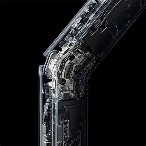
In foldable phones, flex PCBs are used in the hinge area, connecting the two halves of the device. They allow for seamless data and power transfer even when the phone is folded or unfolded thousands of times. The demand for these boards has skyrocketed with the rise of foldable technology, as they solve the challenge of fitting complex electronics into compact, dynamic designs.
Key Flexible PCB Materials for Foldable Phone Applications
The performance of flex PCBs in foldable phones heavily depends on the materials used. These materials must balance flexibility, durability, and electrical performance. Here are the primary materials that make flex PCBs suitable for such demanding applications:
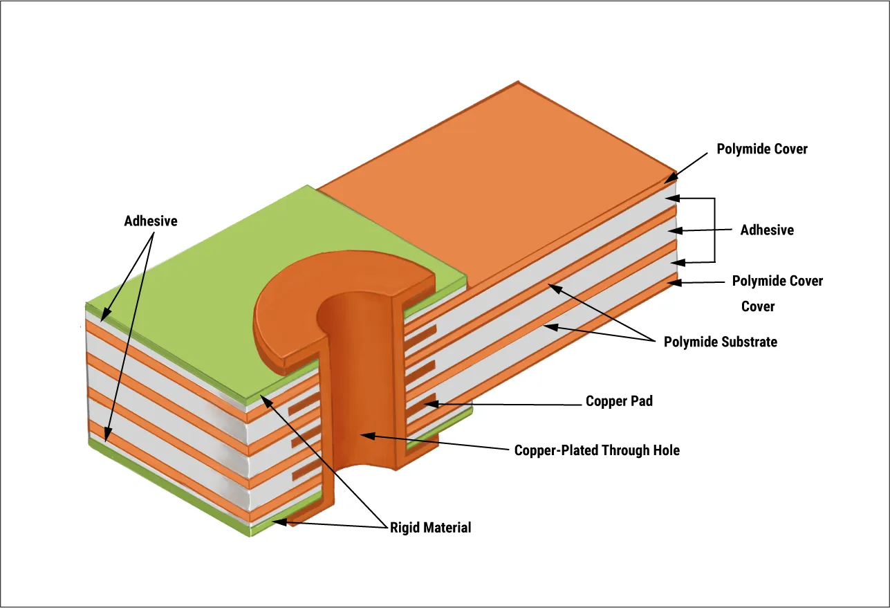
- Polyimide (PI) Film: This is the most common substrate material for flex PCBs due to its excellent thermal stability and flexibility. Polyimide can withstand temperatures up to 400°C and offers a high tensile strength, ensuring the board doesn't tear during repeated bending.
- Copper Foil: Thin layers of copper are used for conductive traces in flex PCBs. Rolled annealed copper is often preferred over electrodeposited copper because it provides better flexibility and fatigue resistance, crucial for dynamic bending in foldable phones.
- Adhesives and Coverlays: Adhesive materials bond the copper to the substrate, while coverlays (protective layers) shield the circuitry. These must be flexible to avoid cracking under stress. Acrylic or epoxy-based adhesives are commonly used for their balance of flexibility and strength.
Choosing the right combination of materials is critical. For instance, a polyimide substrate with a thickness of 12.5 to 25 micrometers paired with 18-micrometer copper foil can achieve a bending radius as low as 0.5 mm, ideal for tight hinge designs in foldable phones.
Foldable Phone Design: How Flexible PCBs Enable Innovation
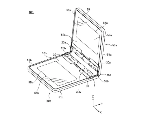
Foldable phone design is a complex puzzle, requiring engineers to integrate displays, batteries, and circuits into a device that folds without breaking. Flexible PCBs play a starring role in this process by providing the necessary connectivity across moving parts. Here’s how they contribute to the design:
- Hinge Connectivity: The hinge is the most critical area in a foldable phone. Flex PCBs are routed through this section, bending with each fold. Designers often use multilayer flex PCBs to accommodate high-density connections while maintaining a slim profile.
- Space Optimization: Traditional rigid boards can't fit into the curved or confined spaces of a foldable phone. Flex PCBs can be shaped to wrap around components, saving space and reducing the device’s overall thickness.
- Signal Integrity: Maintaining signal integrity during bending is a challenge. Flex PCBs are designed with controlled impedance, often around 50 ohms for high-speed signals, to ensure data transfer remains stable even when the phone is folded.
Innovations in foldable phone design also focus on reducing the curvature radius of the hinge. Some designs achieve a folding radius as small as 1.6 mm, which minimizes stress on the flex PCB and extends its lifespan under dynamic conditions.
Flex PCB Manufacturing Process: Crafting Precision for Foldable Phones
Manufacturing flex PCBs for foldable phones is a meticulous process that demands precision at every step. The process differs from rigid PCB manufacturing due to the unique materials and flexibility requirements. Here’s a breakdown of the key stages:
- Material Preparation: The process begins with selecting and preparing materials like polyimide film and copper foil. These are cut into sheets or rolls based on the design specifications.
- Circuit Patterning: Using photolithography, the copper layer is etched to create the circuit traces. This step requires high precision to ensure trace widths as small as 25 micrometers for high-density designs.
- Lamination: Multiple layers of flexible material and copper are laminated together under heat and pressure. Special fixtures are often used to maintain alignment and prevent wrinkling of the thin materials.
- Drilling and Plating: Microvias (tiny holes) are drilled to connect different layers. These vias are then plated with copper to ensure electrical connectivity. Laser drilling is often used for its accuracy in creating holes as small as 50 micrometers.
- Coverlay Application: A protective coverlay is applied over the circuit to shield it from environmental damage and mechanical stress. This layer must be flexible to match the PCB’s bending capability.
- Testing: Finally, the flex PCB undergoes electrical and mechanical testing to ensure it meets performance standards. This includes checking for continuity, impedance (typically targeting 50 ohms for signal lines), and bending endurance.
The manufacturing process is tailored to meet the specific needs of foldable phones, where even a slight defect can lead to failure after a few folds. Advanced facilities often achieve defect rates below 1% through rigorous quality control.
Suggested Reading: Flexible PCB Manufacturing: A Step-by-Step Guide
Rigid-Flex PCB Applications in Foldable Phones and Beyond
While pure flex PCBs are vital for foldable phones, rigid-flex PCBs—a hybrid of rigid and flexible sections—also play a significant role in modern electronics. Rigid-flex PCBs combine the stability of rigid boards with the adaptability of flex circuits, offering unique advantages for complex designs.
In foldable phones, rigid-flex PCBs are often used where certain components require a stable mounting surface (like processors or cameras) while still needing to connect across the folding hinge. For example, a rigid section might house the main chipset, while the flex portion extends through the hinge to connect to the display on the other side.
Beyond foldable phones, rigid-flex PCBs find applications in various industries:
- Wearable Devices: Smartwatches and fitness trackers use rigid-flex PCBs to fit electronics into curved or small form factors.
- Medical Equipment: Devices like portable monitors benefit from rigid-flex designs for compact, reliable circuitry.
- Aerospace: Rigid-flex PCBs are used in satellites and drones, where space and weight savings are critical.
Rigid-flex designs can reduce the need for connectors and cables, cutting down on assembly time and potential failure points. They often achieve a bend radius of 2 mm in flexible sections while maintaining structural integrity in rigid areas.
Dynamic Bending Tests: Ensuring Durability in Foldable Phones
One of the biggest challenges with foldable phones is ensuring that the flex PCB can withstand thousands of folds without failing. This is where dynamic bending tests come into play. These tests simulate real-world usage to evaluate the durability and performance of flex PCBs under stress.
Dynamic bending tests typically involve:
- Cycle Testing: The flex PCB is repeatedly bent and unfolded, often for 100,000 to 200,000 cycles, to mimic years of usage. High-end foldable phones are designed to endure at least 200,000 folds, translating to roughly 100 folds per day over five years.
- Bend Radius Measurement: Tests measure how tight the bend radius can be without causing cracks or signal loss. A smaller radius (e.g., 1.5 mm) indicates better flexibility but higher stress on the material.
- Electrical Performance: During bending, the PCB is tested for continuity and signal integrity. A common benchmark is maintaining impedance within ±10% of the target value (e.g., 50 ohms) after extensive bending cycles.
Manufacturers often use automated testing equipment to apply consistent bending forces and monitor for failures. Innovations in testing methods now include environmental factors like temperature and humidity to simulate real-world conditions, ensuring the flex PCB remains reliable in diverse scenarios.
Future Trends in Flexible PCBs for Foldable Phones
The future of flexible PCBs in foldable phones looks promising, with ongoing innovations aimed at pushing the boundaries of design and durability. Here are a few trends to watch:
- Thinner Materials: Advances in material science are leading to even thinner polyimide films and copper foils, allowing for tighter bend radii and slimmer phone designs.
- Enhanced Durability: New coatings and adhesives are being developed to improve resistance to wear and tear, potentially increasing fold cycles beyond 200,000.
- Integration with Displays: Research is underway to integrate flex PCBs directly with foldable OLED displays, reducing assembly complexity and improving signal transmission speeds.
These advancements will not only enhance foldable phones but also open doors for other flexible electronics, from rollable displays to wearable health monitors.
Conclusion: The Backbone of Foldable Technology
Flexible PCBs are the unsung heroes behind the sleek, innovative designs of foldable phones. From carefully chosen materials like polyimide and copper foil to intricate manufacturing processes and rigorous dynamic bending tests, every aspect of flex PCB design is geared toward durability and performance. Whether it's enabling tight hinge designs in foldable phones or supporting hybrid rigid-flex applications in other devices, these circuit boards are paving the way for the future of electronics.
At ALLPCB, we’re committed to staying at the forefront of these innovations, providing high-quality flexible and rigid-flex PCB solutions tailored to the needs of modern technology. If you're working on a foldable device or any cutting-edge project, understanding the role of flex PCBs is the first step to achieving a successful design.


