ALLPCB


If you’re looking for insights on using flexible PCBs for ultrasound transducer interconnects, you’ve come to the right place. Flexible PCBs, or flex circuits, are a game-changer in ultrasound technology due to their ability to support high-density connections, adapt to dynamic bending, and fit into compact medical devices. In this post, we’ll dive deep into the design and manufacturing considerations for flexible PCBs in ultrasound applications, focusing on key aspects like material selection, signal integrity, and durability under bending stress. Whether you’re an engineer or a designer, this guide will provide actionable information to help you optimize your ultrasound transducer projects.
Why Flexible PCBs Are Ideal for Ultrasound Transducer Interconnects
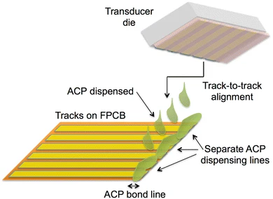
Ultrasound transducers require intricate interconnects to transmit high-frequency signals between the transducer elements and the processing system. Traditional rigid PCBs often fall short in applications where space is limited, and flexibility is needed to conform to curved or irregular shapes. This is where flexible PCBs shine. They offer several advantages:
- Compact Design: Flexible PCBs can be folded or bent, allowing for tighter packaging in handheld or wearable ultrasound devices.
- High-Density Interconnects: They support fine-pitch traces, essential for connecting the numerous elements in modern ultrasound arrays, often exceeding 128 or even 256 channels.
- Durability: Flex circuits can withstand dynamic bending, which is critical for probes that move during scanning.
- Lightweight Construction: Their thin profile reduces the overall weight of portable ultrasound equipment.
With these benefits in mind, let’s explore the specific design and manufacturing considerations for using flexible PCBs in ultrasound applications, targeting needs like high-density flex PCB ultrasound and dynamic bending flex PCB performance.
Key Design Considerations for Flexible PCBs in Ultrasound Applications
Designing a flexible PCB for ultrasound transducer interconnects involves balancing electrical performance with mechanical reliability. Here are the critical factors to consider when working on flex circuit design for ultrasound applications.
1. Material Selection for Flexibility and Performance
The choice of materials is foundational in flexible PCB design. For ultrasound interconnects, the materials must support high-frequency signal transmission while maintaining flexibility. A common choice is polyimide, a material widely used in polyimide flex circuits due to its excellent thermal stability and dielectric properties.
- Base Film: Polyimide films, typically ranging from 12.5 to 50 micrometers in thickness, provide the necessary flexibility and withstand temperatures up to 260°C during soldering processes.
- Copper Foil: Rolled annealed copper, with thicknesses as low as 9 micrometers, is often used for its superior flexibility compared to electrodeposited copper, reducing the risk of cracking under repeated bending.
- Adhesives and Coverlays: Adhesive layers should be minimized or replaced with adhesiveless laminates to reduce thickness and improve bending performance. Coverlays protect the circuit while maintaining a low profile.
Selecting the right materials ensures that the flex PCB can handle the dynamic bending required in ultrasound probes without compromising signal integrity.
2. High-Density Interconnect Design for Ultrasound Arrays
Modern ultrasound transducers often feature high-density arrays with hundreds of individual elements. Achieving reliable high-density flex PCB ultrasound designs requires careful attention to trace width, spacing, and layer stacking.
- Trace Width and Spacing: For high-density interconnects, trace widths as narrow as 50 micrometers and spacing of 50 micrometers are achievable with advanced manufacturing techniques. This allows for connecting dense transducer arrays without increasing the PCB footprint.
- Layer Count: Multi-layer flex PCBs, often with 2 to 6 layers, are used to route signals efficiently. However, increasing layers reduces flexibility, so designers must balance density with mechanical needs.
- Via Design: Microvias with diameters as small as 100 micrometers help maintain high-density routing while minimizing signal loss.
By optimizing these elements, designers can ensure that the flex PCB supports the complex signal paths required for ultrasound imaging without introducing noise or crosstalk.
3. Signal Integrity at High Frequencies
Ultrasound systems operate at frequencies typically ranging from 2 to 20 MHz, depending on the application (e.g., 2-8 MHz for abdominal imaging, 9-20 MHz for superficial imaging). Maintaining signal integrity at these frequencies is critical for accurate imaging.
- Impedance Control: Controlled impedance traces, often targeting 50 ohms for coaxial connections to transducer elements, are essential to minimize signal reflection. This requires precise calculation of trace width and dielectric thickness.
- Dielectric Constant: Polyimide has a dielectric constant of approximately 3.4, which supports stable signal transmission at high frequencies compared to other materials like PET (around 3.2 but less thermally stable).
- Shielding: Incorporating ground planes or shielding layers in the flex PCB design helps reduce electromagnetic interference EMI compliance testing, which can degrade image quality.
Ensuring signal integrity directly impacts the performance of the ultrasound system, making it a top priority in flex circuit design for ultrasound.

4. Dynamic Bending and Mechanical Reliability
Ultrasound probes often undergo repeated bending during use, especially in handheld or flexible patch applications. Designing for dynamic bending in flex PCBs is crucial to prevent failures like trace cracking or delamination.
- Bend Radius: The minimum bend radius should be at least 10 times the thickness of the flex PCB. For a 0.1 mm thick board, this means a minimum bend radius of 1 mm to avoid stress concentration.
- Balanced Stack-Up: A symmetrical layer stack-up, with copper and dielectric layers evenly distributed, reduces stress during bending. For instance, placing conductors in the neutral axis (center of the stack) minimizes strain.
- Bending Cycles: High-quality dynamic bending flex PCBs can withstand over 100,000 bending cycles if designed with thin materials and proper reinforcement.
By focusing on these mechanical aspects, designers can extend the lifespan of the flex PCB in demanding ultrasound applications.
Manufacturing Considerations for Flexible PCBs in Ultrasound Interconnects
Manufacturing flexible PCBs for ultrasound transducers requires precision and adherence to strict quality standards. Here are the key considerations to ensure the final product meets performance and reliability expectations.
1. Precision Fabrication for High-Density Designs
High-density flex PCB ultrasound designs demand advanced fabrication techniques to achieve fine traces and small vias. Manufacturers must use processes like laser drilling for microvias and photolithography for precise trace patterning. Tolerances for trace width and spacing should be within ±10% to maintain electrical performance. Additionally, automated optical inspection AOI inspection ensures that no defects, such as open circuits or shorts, compromise the interconnects.
2. Material Handling and Lamination
Flexible materials like polyimide are prone to wrinkling or stretching during manufacturing, which can distort traces and affect performance. Proper tension control during lamination and the use of low-stress adhesives are critical to maintaining dimensional stability. For multi-layer designs, aligning layers with a tolerance of ±50 micrometers is necessary to prevent signal misalignment in high-density interconnects.
3. Testing for Electrical and Mechanical Performance
Before deployment, flexible PCBs must undergo rigorous testing to verify both electrical and mechanical properties:
- Electrical Testing: Impedance testing ensures that traces meet the target value (e.g., 50 ohms) with a tolerance of ±10%. High-frequency testing at ultrasound operating frequencies (2-20 MHz) confirms signal integrity.
- Mechanical Testing: Bend cycle testing, often exceeding 10,000 cycles, verifies durability under dynamic conditions. Environmental testing, including thermal cycling from -40°C to 85°C, ensures reliability in varied conditions.
These tests guarantee that the flex PCB can handle the real-world demands of ultrasound applications.
4. Compliance with Medical Standards
Ultrasound devices are medical equipment, so flexible PCBs must comply with standards like ISO 13485 for quality management and IEC 60601 for medical electrical equipment safety. Biocompatibility of materials is also a concern if the flex PCB comes into contact with the patient’s skin. Using RoHS-compliant materials ensures that no hazardous substances are present, aligning with global safety regulations.
Suggested Reading: Flexible PCB Manufacturing: A Step-by-Step Guide
Applications of Flexible PCBs in Ultrasound Technology
Flexible PCBs are transforming ultrasound technology across various applications, thanks to their adaptability and performance. Some notable uses include:
- Handheld Ultrasound Devices: Flex circuits enable compact, lightweight designs for portable scanners used in emergency and point-of-care settings.
- Wearable Ultrasound Patches: Emerging flexible ultrasound patches for continuous monitoring rely on dynamic bending flex PCBs to conform to the body’s contours.
- Endoscopic Ultrasound Probes: Flex PCBs allow for miniaturized interconnects in probes that navigate tight spaces within the body.
These applications highlight the versatility of flexible PCBs and their critical role in advancing medical imaging technology.
Challenges and Solutions in Flexible PCB Design for Ultrasound
While flexible PCBs offer numerous benefits, they come with challenges that designers and manufacturers must address:
- Challenge - Cost: High-density flex PCBs with fine traces and multiple layers can be expensive to produce.
Solution: Optimize designs to minimize layer count and use cost-effective materials without sacrificing performance. - Challenge - Signal Loss: Thin traces and long interconnects can introduce signal attenuation at high frequencies.
Solution: Use low-loss dielectrics and incorporate repeaters or amplifiers if necessary. - Challenge - Mechanical Failure: Repeated bending can lead to fatigue and cracking.
Solution: Reinforce bending areas with stiffeners and design with generous bend radii.
Addressing these challenges ensures that flexible PCBs deliver reliable performance in ultrasound transducer interconnects.
Conclusion: Optimizing Flexible PCBs for Ultrasound Success
Flexible PCBs are a vital component in the evolution of ultrasound technology, offering unmatched advantages in compactness, high-density interconnects, and dynamic bending capabilities. By focusing on key design considerations like material selection, signal integrity, and mechanical reliability, and by adhering to precise manufacturing processes, engineers can create interconnects that meet the demanding requirements of modern ultrasound systems. Whether you’re developing handheld devices or wearable patches, understanding the nuances of flex circuit design for ultrasound applications is essential for success.
At ALLPCB, we’re committed to supporting your projects with high-quality flexible PCB solutions tailored to your needs. With a focus on precision and innovation, we help bring your ultrasound designs to life with reliable, high-performance interconnects.