 ALLPCB


In the fast-evolving world of electronics, thermal management is a critical aspect of design. As components become smaller and more powerful, heat dissipation becomes increasingly important to ensure reliability and performance. This blog post dives deep into the essentials of PCB heatsink design and selection, offering practical guidance for engineers and designers. Whether you're working on a high-power circuit or a compact device, understanding the heatsink selection process can make a significant difference in your project's success.
At its core, a heatsink is a passive cooling solution that transfers heat away from critical components on a printed circuit board (PCB). By choosing the right design and materials, you can prevent overheating, extend component lifespan, and improve overall system efficiency. In the sections below, we’ll explore the fundamentals of heatsink design, key factors in the selection process, and actionable tips to optimize thermal management in your PCB projects.
Why Thermal Management Matters in PCB Design
Modern electronics generate significant heat, especially in applications like power supplies, LED lighting, and high-performance computing. Without proper thermal management, excessive heat can degrade components, cause system failures, or reduce efficiency. For instance, a typical power IC can reach temperatures above 100°C under load, far exceeding safe operating limits of 85°C for many components. Effective heat dissipation becomes increasingly important as power densities rise in compact designs.
Thermal management is not just about preventing damage; it also ensures consistent performance. Overheating can lead to thermal throttling, where components reduce output to avoid damage, impacting system functionality. By incorporating a well-designed heatsink, you can maintain optimal temperatures, ensuring your PCB operates reliably under various conditions.
Understanding the Basics of Heatsink Functionality
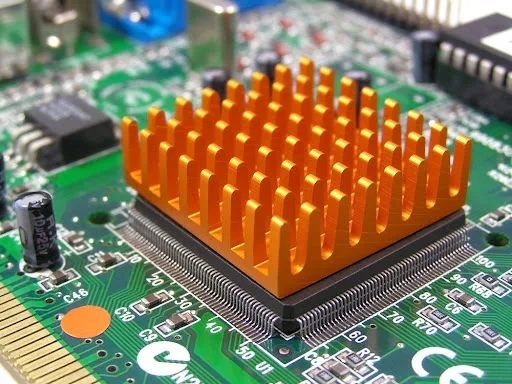
A heatsink works by increasing the surface area available for heat dissipation. It absorbs heat from a component through conduction, then transfers it to the surrounding air via convection or radiation. The efficiency of this process depends on the heatsink's material, design, and mounting method.
Heat transfer in a PCB environment involves three primary modes:
- Conduction: Heat moves from the component to the heatsink through direct contact. Materials with high thermal conductivity, like aluminum or copper, excel in this area.
- Convection: Heat is dissipated into the air as it flows over the heatsink’s surface. Designs with fins or pins increase surface area, enhancing convection.
- Radiation: Heat is emitted as infrared energy. While less significant in most PCB applications, surface treatments like black anodizing can improve radiation efficiency.
Understanding these principles is the foundation of effective heatsink design. For example, a heatsink with a thermal conductivity of 200 W/m·K (common for aluminum) can transfer heat much faster than one with a lower value, directly impacting cooling performance.
Key Factors in PCB Heatsink Design
Designing a heatsink for a PCB involves balancing multiple factors to achieve optimal thermal performance. Below are the critical elements to consider:
1. Material Selection
The choice of material directly affects a heatsink’s ability to conduct and dissipate heat. Common materials include:
- Aluminum: Lightweight and cost-effective, with a thermal conductivity of around 200-230 W/m·K. It’s ideal for most PCB applications.
- Copper: Offers superior thermal conductivity (about 400 W/m·K) but is heavier and more expensive. It’s often used in high-power designs.
- Composite Materials: Some advanced heatsinks use graphite or ceramic composites for specific applications, though they are less common in standard PCB designs.
For a typical PCB with moderate heat output (e.g., 5-10W per component), aluminum provides a good balance of performance and cost. However, for high-power components exceeding 20W, copper may be necessary despite the added weight.
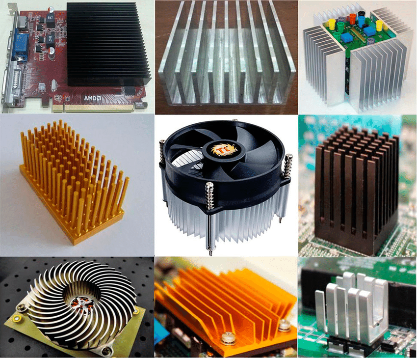
2. Heatsink Geometry and Surface Area
The shape and size of a heatsink determine how effectively it can dissipate heat. Common designs include:
- Fin Structures: Vertical or horizontal fins increase surface area for convection. A fin spacing of 2-3mm often optimizes airflow in natural convection setups.
- Pin Fin Arrays: These provide omnidirectional cooling, ideal for forced convection environments with fans.
- Flat Plate Designs: Simple and compact, these are suitable for low-power components or space-constrained PCBs.
The surface area should match the heat load. For instance, a component dissipating 15W might require a heatsink with at least 100 cm2 of surface area to keep temperatures below 85°C in ambient conditions of 25°C.
3. Thermal Interface Materials (TIM)
The connection between the component and heatsink is critical for efficient heat transfer. Thermal interface materials, such as thermal paste or pads, fill microscopic gaps, reducing thermal resistance. A high-quality TIM can lower thermal resistance by 0.5-1.0°C/W, significantly improving cooling efficiency.
4. Mounting and Placement
How a heatsink is mounted affects both thermal performance and mechanical stability. Common methods include adhesive bonding, screw mounting, and clip systems. Ensure the heatsink is placed directly over the heat-generating component with minimal thermal resistance in the path. Additionally, consider airflow patterns on the PCB—positioning a heatsink in an area with restricted airflow can reduce its effectiveness by up to 30%.
The Heatsink Selection Process: A Step-by-Step Guide
Choosing the right heatsink for your PCB project can be daunting, but a structured approach simplifies the process. Follow these steps to ensure optimal thermal management:
Step 1: Calculate Heat Load
Start by determining the heat output of the components that need cooling. Use manufacturer datasheets to find the power dissipation (in watts) for each component. For example, a power MOSFET might dissipate 8W under full load. Sum the heat loads of all critical components to estimate the total thermal demand.
Step 2: Assess Ambient Conditions
Consider the operating environment of your PCB. Ambient temperature, airflow availability, and enclosure design all impact heatsink performance. A device operating in a 40°C environment with no forced airflow will require a larger heatsink compared to one in a 25°C setting with a cooling fan.
Step 3: Determine Thermal Resistance Requirements
Thermal resistance (°C/W) measures how much a heatsink resists heat flow. To keep a component at a safe temperature, calculate the required thermal resistance using the formula:
Thermal Resistance = (Max Component Temp - Ambient Temp) / Power Dissipation
For instance, if a component must stay below 85°C in a 25°C environment and dissipates 10W, the required thermal resistance is (85-25)/10 = 6°C/W. Choose a heatsink with a thermal resistance equal to or lower than this value.
Step 4: Evaluate Space and Weight Constraints
Ensure the heatsink fits within the PCB layout and enclosure. A large heatsink might offer excellent cooling but could interfere with other components or add excessive weight. For compact designs, consider low-profile heatsinks or alternative cooling methods like thermal vias.
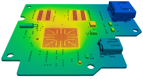
Step 5: Test and Validate
Once a heatsink is selected, prototype and test the design under real-world conditions. Use thermal imaging or temperature sensors to verify that component temperatures remain within safe limits (typically below 85-100°C for most ICs). Adjust the design if necessary, such as by increasing fin height or adding forced airflow.
Advanced Techniques for Enhanced Heat Dissipation
Beyond basic heatsink design, several advanced strategies can further improve thermal management in high-performance PCBs:
1. Thermal Vias
Thermal vias are small holes filled with conductive material (usually copper) that transfer heat from a component to the opposite side of the PCB or to a larger copper plane. Placing 10-15 thermal vias under a high-power component can reduce thermal resistance by 20-30%, effectively spreading heat across a wider area.
2. Copper Planes and Traces
Increase the copper thickness in areas near heat-generating components to act as a heat spreader. A 2oz copper layer (compared to the standard 1oz) can improve heat dissipation by up to 50% in some designs, reducing the reliance on external heatsinks.
3. Forced Convection with Fans
For applications with extreme heat loads, combine heatsinks with active cooling solutions like fans. A small fan providing 10-20 CFM (cubic feet per minute) of airflow can lower temperatures by 15-25°C compared to natural convection alone.
Common Mistakes to Avoid in Heatsink Design and Selection
Even experienced engineers can make errors in thermal management. Here are pitfalls to watch out for:
- Underestimating Heat Load: Failing to account for worst-case scenarios can lead to undersized heatsinks, causing overheating. Always add a safety margin of 20-30% to calculated heat loads.
- Poor TIM Application: Applying too much or too little thermal paste can create air gaps, increasing thermal resistance by 1-2°C/W.
- Ignoring Airflow: Placing a heatsink in a stagnant air zone reduces convection efficiency. Ensure there’s adequate space around the heatsink for air circulation.
Conclusion: Mastering PCB Heatsink Design for Optimal Performance
Thermal management is a critical aspect of design in today’s high-performance electronics, and heatsinks play a vital role in ensuring reliable operation. As heat dissipation becomes increasingly important with advancing technology, understanding the nuances of heatsink design and the selection process is essential for engineers. By carefully considering material choices, geometry, thermal resistance, and environmental factors, you can create PCB designs that handle heat effectively and maintain long-term reliability.
Whether you’re tackling a simple low-power circuit or a complex high-density board, the principles outlined in this guide provide a roadmap to success. Start with accurate heat load calculations, choose the right heatsink for your needs, and validate your design through testing. With these steps, you’ll be well-equipped to manage thermal challenges and build robust, efficient PCB systems.


