ALLPCB


If you're an electrical engineer working with high-resolution Analog-to-Digital Converters (ADCs), selecting the right precision op-amp is critical to achieving accurate and reliable data. The key to success lies in minimizing noise and offset errors, which can degrade the performance of even the best ADCs. In this guide, we'll dive into how to choose a low noise op amp for ADC applications, address op amp offset voltage compensation, and explore the role of a precision amplifier for data acquisition. We'll also cover op amp settling time for ADC accuracy and the importance of a high-resolution ADC driver. Let’s get started with ALLPCB to help you optimize your designs.
Why Precision Op-Amps Matter for High-Resolution ADCs
High-resolution ADCs, often ranging from 16 to 24 bits, are designed to capture minute signal variations with extreme accuracy. However, their performance heavily depends on the analog front-end circuitry, particularly the operational amplifier (op-amp) driving the ADC input. A poorly chosen op-amp can introduce noise, offset errors, and distortion, rendering the ADC’s high resolution useless.
For instance, imagine you're designing a data acquisition system for a medical device that measures tiny bioelectric signals. Even a small offset error of 1 mV or added noise of 5 nV/√Hz can skew readings, leading to inaccurate diagnoses. This is why selecting a precision op-amp with low noise and minimal offset is non-negotiable.
Key Factors in Selecting a Low Noise Op-Amp for ADC
When choosing a low noise op amp for ADC applications, noise performance is your top priority. Noise from the op-amp can directly limit the effective number of bits (ENOB) of your ADC, reducing resolution. Let’s break down the critical parameters to consider:
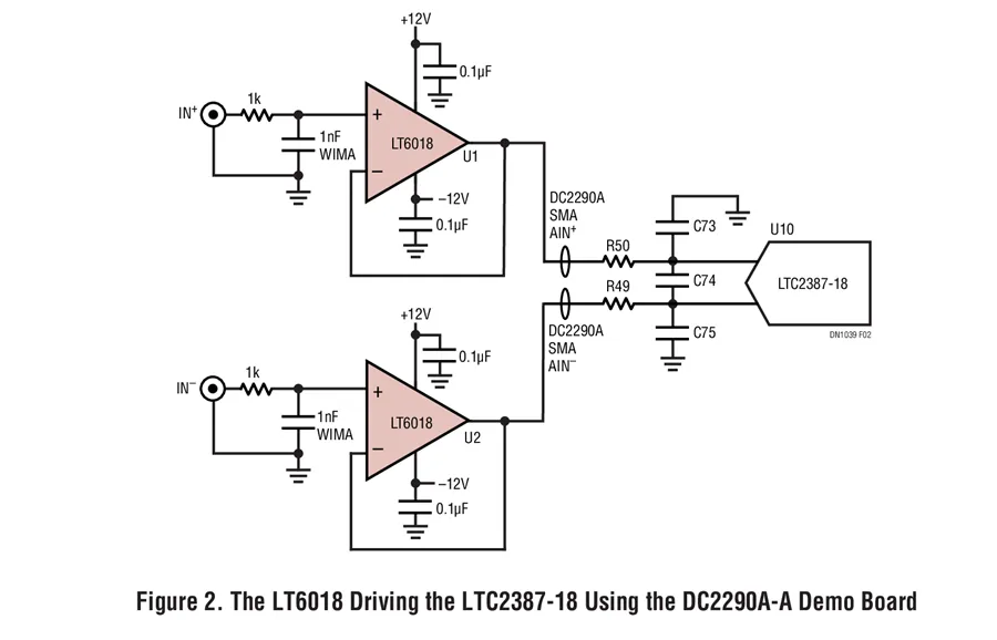
- Input Voltage Noise: Look for op-amps with low input voltage noise, ideally below 5 nV/√Hz at 1 kHz. For example, the LT6018 from Analog Devices offers an ultralow noise of 1.2 nV/√Hz, making it a great choice for driving high-resolution SAR ADCs.
- Current Noise: Input current noise becomes significant in high-impedance circuits. Choose an op-amp with low input bias current (e.g., less than 1 pA) to minimize this effect.
- Bandwidth: Ensure the op-amp’s gain-bandwidth product supports the ADC’s sampling rate. For a 1 MSPS ADC, an op-amp with a gain-bandwidth of at least 10 MHz is often necessary to avoid signal distortion.
By prioritizing these specs, you can prevent noise from masking the small signals your high-resolution ADC is meant to detect.
Understanding and Implementing Op-Amp Offset Voltage Compensation
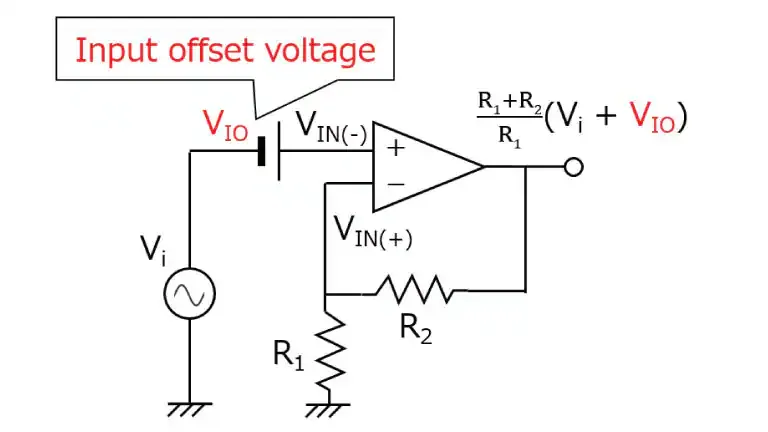
Offset voltage is another critical error source in precision applications. Even a small offset voltage in the op-amp can cause a constant error in the ADC output, especially in DC-coupled systems. This is where op amp offset voltage compensation techniques come into play.
Most precision op-amps, like those in Texas Instruments’ portfolio with input offset voltages (Vos) below 1 mV, are designed to minimize this issue. However, additional compensation may still be needed for ultra-high accuracy. Here are two practical approaches:
- Hardware Compensation: Use a trimming circuit with a potentiometer or digital-to-analog converter (DAC) to nullify the offset. For example, in a 24-bit ADC system, an offset of 500 μV can shift readings by several least significant bits (LSBs). A simple resistor network tied to the op-amp’s input can adjust this.
- Software Calibration: Capture the offset during a calibration phase and subtract it digitally in your microcontroller or DSP. This method works well for systems where environmental conditions (like temperature) cause offset drift.
By implementing these techniques, you can ensure your ADC readings remain accurate even in demanding applications like industrial sensors or scientific instruments.
The Role of a Precision Amplifier for Data Acquisition
A precision amplifier for data acquisition acts as the bridge between your sensor or signal source and the ADC. Its job is to condition the input signal—amplifying it, filtering noise, and ensuring the voltage levels match the ADC’s input range. Without a high-quality precision amplifier, small signals can be lost in noise or clipped due to improper scaling.
Consider a strain gauge application where the output is a mere 10 mV full-scale. A precision amplifier with a gain of 100 can boost this to 1 V, fitting neatly within a 2.5 V ADC input range. However, the amplifier must have low drift and high common-mode rejection ratio (CMRR) of at least 100 dB to reject interference from nearby power lines or motors.
When selecting an amplifier, also check its linearity. Nonlinearity in the amplifier can introduce harmonic distortion, which a high-resolution ADC will faithfully digitize, leading to erroneous data. Look for op-amps with total harmonic distortion (THD) below -100 dB for best results.
Op-Amp Settling Time for ADC Accuracy
Another often-overlooked parameter is the op amp settling time for ADC accuracy. Settling time refers to how quickly the op-amp output stabilizes after a step change in input. For high-speed ADCs, especially successive approximation register (SAR) types, the op-amp must settle to within 0.5 LSB of the final value before the ADC samples the signal.
For a 16-bit ADC with a 5 V reference, 1 LSB is approximately 76 μV. If the op-amp takes too long to settle—say, 1 μs when the ADC samples every 500 ns—it will sample an inaccurate voltage, leading to errors. Choose an op-amp with a settling time faster than the ADC’s acquisition window. For instance, an op-amp with a settling time of 100 ns to 0.01% accuracy is ideal for ADCs sampling at 1 MSPS.
Additionally, pay attention to the op-amp’s slew rate. A slew rate of at least 10 V/μs ensures the op-amp can handle rapid signal changes without introducing errors. This is especially critical in applications like audio processing or fast sensor measurements.
Choosing a High-Resolution ADC Driver
The op-amp often serves as a high-resolution ADC driver, tasked with delivering a stable, low-impedance signal to the ADC input. Many high-resolution ADCs have switched-capacitor inputs that draw transient currents during sampling. If the driver op-amp can’t supply this current quickly, the input voltage will droop, causing errors.
To avoid this, select an op-amp with high output current capability (e.g., 20 mA or more) and low output impedance. Fully differential op-amps, like the LTC6362 from Analog Devices, are excellent choices for driving differential ADCs. They provide balanced outputs, reject common-mode noise, and maintain signal integrity even at high frequencies.
Also, consider adding a low-pass RC filter between the op-amp and ADC to limit bandwidth and reduce noise. For a 24-bit ADC sampling at 100 kSPS, a filter with a cutoff frequency of 50 kHz can effectively suppress high-frequency noise while preserving the signal of interest.
Practical Tips for Minimizing Noise and Offset Errors
Here are some actionable tips to ensure your op-amp and ADC pairing delivers the best performance:
- Power Supply Decoupling: Use bypass capacitors (e.g., 0.1 μF ceramic and 10 μF tantalum) close to the op-amp’s power pins to filter out supply noise. Noise on the supply line can couple into the signal path, degrading ADC performance.
- PCB Layout: Keep analog and digital grounds separate to prevent digital switching noise from contaminating the analog signal. Route sensitive traces away from high-current or high-frequency lines.
- Temperature Stability: Choose op-amps with low thermal drift (e.g., 0.5 μV/°C for offset voltage) if your application operates across a wide temperature range, such as in automotive or outdoor systems.
- Simulation and Testing: Use SPICE simulations to model your op-amp and ADC circuit before building. Test the prototype with a signal generator to measure noise and offset under real-world conditions.
Suggested Reading:Optimizing Op-Amp PCB Layout for EMI Reduction in Sensitive Analog Circuits
Real-World Example: Designing for a 24-Bit ADC System
Let’s walk through a practical example. Suppose you’re designing a system with a 24-bit delta-sigma ADC for precision weight measurement. The sensor outputs a differential signal of ±10 mV, and the ADC has a 2.5 V reference and samples at 100 SPS.
First, select a precision op-amp like the AD8421, which offers low noise (3 nV/√Hz) and high CMRR (126 dB). Configure it as a differential amplifier with a gain of 100 to scale the input to ±1 V, fitting within the ADC’s range. Add a low-pass filter with a 50 Hz cutoff to reject power line interference. Finally, ensure the op-amp’s settling time is under 10 ms (given the low sampling rate) to avoid errors.
During testing, measure the system’s noise floor. If the total noise exceeds 1 LSB (about 0.3 μV for a 2.5 V, 24-bit ADC), consider a quieter op-amp or additional shielding. This systematic approach ensures your design achieves the full resolution of the ADC.
Common Pitfalls to Avoid
Even with the best components, mistakes in design or selection can undermine performance. Watch out for these common issues:
- Underestimating Noise Sources: Don’t just focus on the op-amp’s noise spec—consider external sources like EMI compliance testing or thermal noise from resistors. Use low-noise resistors (e.g., 0.1% tolerance metal film) in critical paths.
- Ignoring ADC Input Requirements: Some ADCs require specific input voltage ranges or impedance. Mismatched drivers can cause signal clipping or excessive loading.
- Overlooking Environmental Factors: Temperature, humidity, and vibration can affect op-amp performance. Always test under expected operating conditions.
Conclusion: Building Better ADC Systems with Precision Op-Amps
Selecting the right precision op-amp for high-resolution ADCs is a balancing act of minimizing noise, compensating for offset errors, and ensuring fast settling times. By focusing on key parameters like input noise (below 5 nV/√Hz), offset voltage (under 1 mV), and settling time (faster than the ADC’s acquisition window), you can maximize the accuracy of your data acquisition system. Whether you’re choosing a low noise op amp for ADC, implementing op amp offset voltage compensation, or designing a high-resolution ADC driver, the principles outlined here will guide you to success.