 ALLPCB


Printed circuit boards (PCBs) are the backbone of modern electronics, and choosing the right material is critical for performance, especially in demanding applications. Advanced materials like Polytetrafluoroethylene (PTFE) and Polyimide (PI) offer unique properties that make them ideal for specialized industries such as aerospace, medical, and telecommunications. In this blog, we explore the characteristics, applications, and benefits of PTFE and Polyimide, helping engineers make informed decisions for their next project.
Whether you're designing high-frequency circuits or flexible electronics, understanding these materials can elevate your PCB performance. Let's dive into why PTFE and Polyimide are game-changers in PCB manufacturing.
Understanding PTFE: The High-Frequency Champion
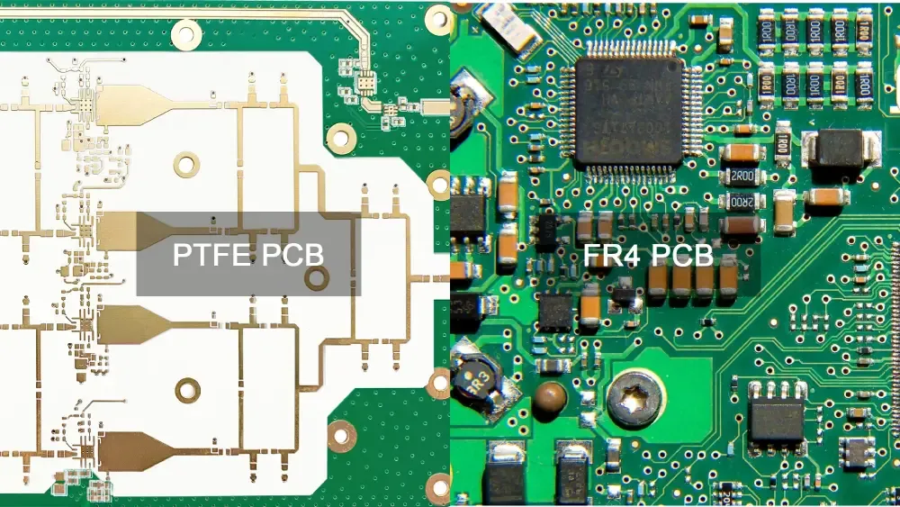
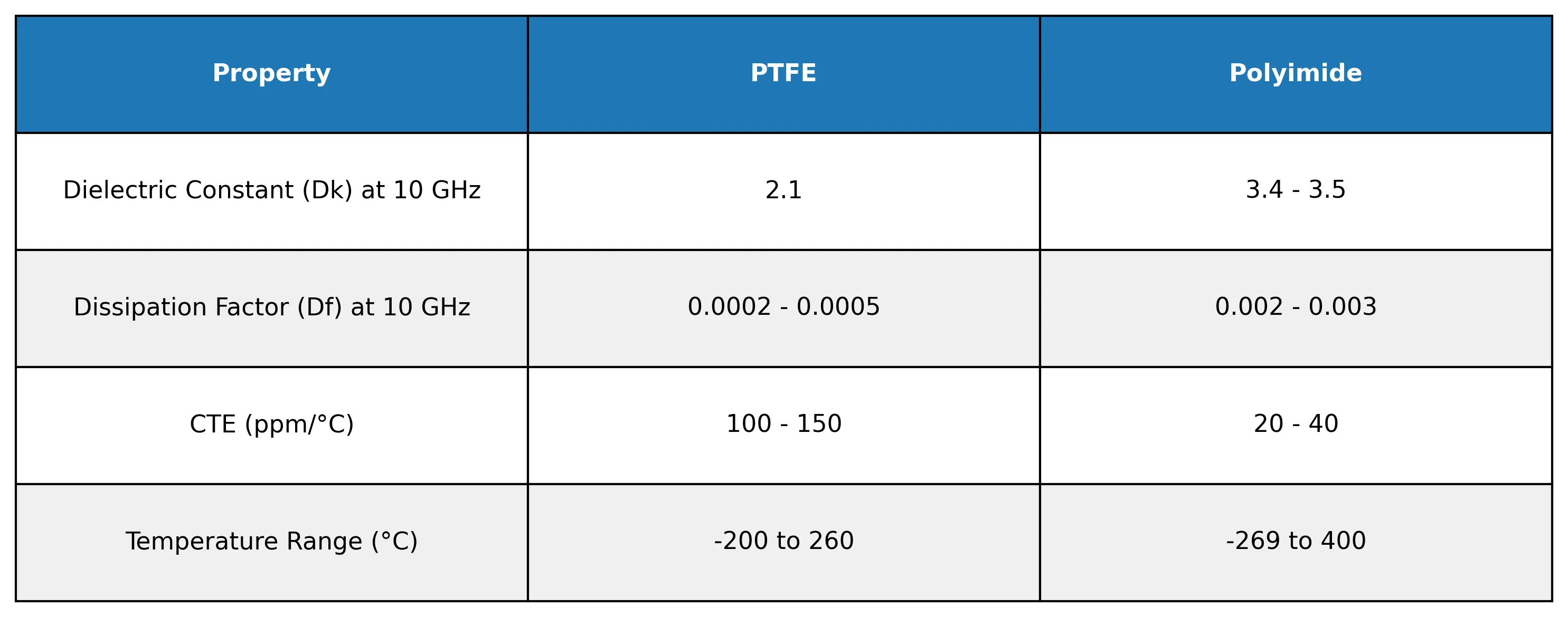
PTFE, commonly known as Teflon, is a fluoropolymer celebrated for its exceptional electrical properties. Its low dielectric constant (Dk) of approximately 2.1 at 10 GHz and low dissipation factor (Df) of 0.0002 to 0.0005 make it a top choice for high-frequency applications. These properties ensure minimal signal loss, which is crucial for RF and microwave circuits used in radar systems, satellite communications, and 5G modules.
PTFE's thermal stability allows it to withstand temperatures up to 260°C, making it suitable for harsh environments like aerospace and industrial process control. Additionally, its chemical resistance ensures durability when exposed to oils, grease, or corrosive reagents, enhancing reliability in medical devices and military equipment.
However, PTFE's softness requires specialized manufacturing processes, such as controlled lamination and precise drilling, to maintain dimensional stability. These challenges can increase the custom PCB board cost, but the performance benefits often outweigh the expense for critical applications.
Polyimide: The Flexible Powerhouse
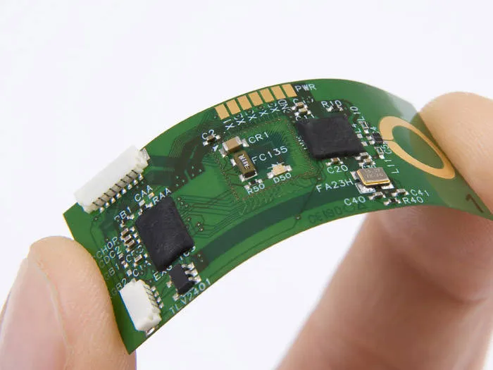
Polyimide is a high-performance polymer renowned for its flexibility, thermal stability, and mechanical strength. With a glass transition temperature exceeding 300°C, Polyimide PCBs can operate in extreme conditions, from -269°C to 400°C, making them ideal for aerospace, automotive, and medical applications.
Its flexibility is a key advantage, enabling the production of flexible and rigid-flex PCBs. For example, Polyimide-based PCBs are used in wearable devices like fitness trackers, where the board must bend to fit compact designs. In automotive applications, such as engine control units, Polyimide withstands high temperatures and vibrations, ensuring long-term reliability.
Polyimide also offers excellent dielectric strength, preventing electrical interference in medical devices like pacemakers. Its low coefficient of thermal expansion (CTE) minimizes warping, maintaining signal integrity with impedance values as precise as 50 ohms in high-density interconnect (HDI) designs.
Comparing PTFE and Polyimide: Key Differences
While both PTFE and Polyimide excel in specialized applications, their properties cater to different needs. PTFE's low Dk and Df make it superior for high-frequency signals, with signal speeds up to 10 GHz in RF circuits. Polyimide, however, is better suited for applications requiring flexibility and mechanical durability, such as multilayer flex PCBs with up to 10 layers.
Cost is another differentiator. PTFE is more expensive due to its complex processing, with material costs up to 3 times higher than standard FR-4. Polyimide is also pricier than FR-4 but offers a cost-effective balance for flexible designs. For instance, a 4-layer Polyimide flex PCB is commonly used in telecom applications, costing approximately 20-30% more than an equivalent FR-4 board.
Manufacturing considerations also vary. PTFE requires specialized lamination techniques to prevent creep, while Polyimide demands careful handling to manage its higher CTE (20-40 ppm/°C) compared to FR4 (14-18 ppm/°C). Engineers must weigh these factors against project requirements, such as operating temperature and signal integrity.
Applications Driving PTFE and Polyimide Adoption
Aerospace and Defense
In aerospace, PTFE and Polyimide are indispensable. PTFE's low dielectric loss ensures reliable signal transmission in satellite communication systems, where signals must travel with minimal attenuation. Polyimide's thermal stability and lightweight properties are critical for avionics, reducing aircraft weight by up to 1/3 compared to rigid FR-4 boards.
Medical Devices
Medical implants like defibrillators rely on Polyimide's biocompatibility and flexibility. Its high dielectric strength (up to 4000 V/mil) ensures patient safety by preventing electrical interference. PTFE is used in diagnostic equipment, such as MRI systems, where its chemical resistance protects against sterilization processes.
Telecommunications
The rise of 5G has increased demand for PTFE-based PCBs in base stations, where low-loss materials support high-frequency signals at 3.5 GHz and beyond. Polyimide HDI PCBs enable compact designs in smartphones, accommodating fine-pitch traces as small as 5 mils.
Design and Manufacturing Considerations
Designing with PTFE and Polyimide requires attention to material properties. For PTFE, engineers must account for its softness, using nesting fixtures during lamination to maintain trace alignment within 0.1 mm. Polyimide's flexibility necessitates supportive tools during surface-mount technology (SMT) assembly to prevent deformation.
Testing is critical for both materials. PTFE PCBs undergo Time Domain Reflectometry (TDR) impedance tests to ensure 50-ohm controlled impedance, while Polyimide PCBs are subjected to peel strength tests to verify conductor adhesion. Storage is also important; Polyimide PCBs require a humidity-controlled environment to prevent moisture absorption, with a shelf life of 3-6 months.
Surface finishes like Electroless Nickel Immersion Gold (ENIG) are recommended for both materials to enhance solderability and protect copper traces. These finishes ensure reliable connections in high-reliability applications.

How ALLPCB Supports Your Advanced PCB Needs
At ALLPCB, we understand the challenges of working with advanced materials like PTFE and Polyimide. Our quick-turn prototyping services enable engineers to test designs rapidly, with lead times as short as 24 hours for single-layer boards. Our global logistics network ensures timely delivery, while our advanced manufacturing facilities support specialized processes like controlled lamination and precise drilling. Whether you're developing a high-frequency RF board or a flexible medical device, we provide tailored solutions to meet your project's demands.
Conclusion: Choosing the Right Material for Your Project
PTFE and Polyimide are transformative materials that address the needs of high-performance electronics. PTFE excels in high-frequency applications, offering unmatched signal integrity, while Polyimide delivers flexibility and durability for compact, rugged designs. By understanding their properties and applications, engineers can select the right material to optimize performance and reliability.
As electronics continue to evolve, the demand for advanced PCB materials will grow. Whether you're pushing the boundaries of 5G or designing life-saving medical devices, PTFE and Polyimide provide the foundation for success. Partner with a trusted manufacturer like ALLPCB to bring your vision to life with precision and efficiency.





