ALLPCB


Automotive electronics demand printed circuit boards that perform reliably under extreme conditions. Modern vehicles integrate dozens of electronic control units for powertrain management, advanced driver assistance systems, infotainment, and battery monitoring in electric models. Engineers rely on specialized PCB design software to manage complex multilayer layouts, signal integrity requirements, and thermal constraints while meeting strict industry standards. Effective tools help teams reduce iteration cycles and accelerate time to market without compromising quality.
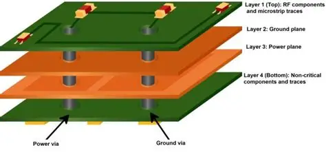
Automotive environments expose PCBs to wide temperature swings, constant vibration, moisture, and electromagnetic interference. These factors require design approaches that go beyond consumer electronics standards. Best PCB design software automotive solutions provide integrated environments for schematic capture, layout, and simulation that address these challenges from the start. PCB design tools for transportation must support high current traces, robust grounding schemes, and component placement strategies that minimize stress concentrations.
Why PCB Design Software Matters for Automotive Applications
Without capable software, teams face repeated respins when prototypes fail vibration testing or thermal cycling. Structured workflows in professional tools allow early detection of issues such as excessive trace inductance or inadequate copper balancing. This proactive approach supports the high reliability expected in safety critical systems.
Core Technical Capabilities Required in Automotive PCB Design Tools
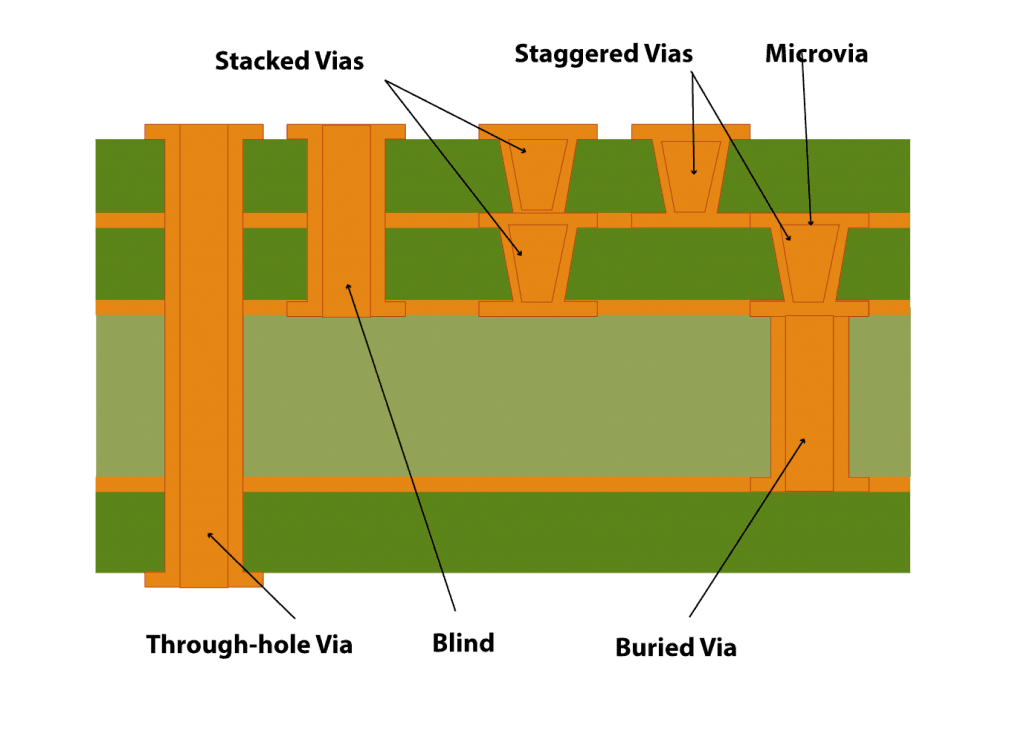
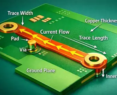
Effective automotive PCB design begins with accurate schematic capture that captures all functional requirements and safety classifications. Engineers then translate these into physical layouts while enforcing design rules for minimum trace widths, clearances, and via structures suited to high reliability applications. Advanced tools incorporate simulation engines that model signal integrity, power distribution, and thermal behavior before fabrication.
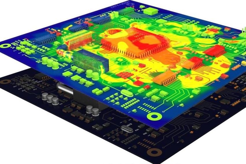
Thermal analysis helps predict hot spots in power electronics modules where high current densities occur. Vibration and mechanical stress modeling assists with component placement to avoid fatigue in solder joints over the vehicle lifetime. These capabilities reduce the risk of field failures that could affect vehicle performance or occupant safety.
Best Practices for Streamlining the Automotive PCB Design Workflow
Teams achieve efficiency by establishing consistent design rule sets early in the project that align with target manufacturing capabilities and end use conditions. Version control and collaboration features allow multiple engineers to work on the same project while maintaining traceability of changes. Regular design reviews at schematic and layout stages catch potential issues before they reach fabrication.
Component libraries should include automotive qualified parts with verified footprints and 3D models to support accurate mechanical integration. Simulation results guide iterative improvements to stack up, copper distribution, and shielding strategies. Documentation generated directly from the design database ensures that manufacturing and quality teams receive complete, accurate data packages.
Compliance and Quality Considerations in Automotive PCB Projects
Automotive PCB designs must satisfy rigorous qualification requirements to ensure long term reliability. Industry standards provide the framework for material selection, construction, and acceptance criteria. IPC 6012E defines performance specifications for rigid printed boards used in demanding applications. J STD 001 establishes requirements for soldered electrical and electronic assemblies that directly influence joint reliability under thermal and mechanical stress.
Design software supports compliance by allowing rule checks against these standards and by generating reports that document adherence to specified criteria. Early verification of manufacturability reduces the likelihood of non conformances during production. Consistent application of these practices across projects builds confidence in the final product.
Conclusion
Specialized PCB design software enables engineering teams to address the unique demands of automotive electronics with greater speed and precision. By integrating schematic, layout, simulation, and documentation functions, these tools support the development of boards that meet performance, reliability, and regulatory expectations. Structured workflows and adherence to established standards help minimize costly iterations while delivering designs ready for volume production in transportation applications.
FAQs
Q1: What makes PCB design software essential for automotive projects?
A1: Automotive PCBs operate in harsh conditions that require careful attention to thermal management, vibration resistance, and electromagnetic compatibility. Best PCB design software automotive platforms provide simulation and rule checking capabilities that help engineers meet these requirements efficiently while maintaining traceability throughout the design process.
Q2: How do PCB design tools for transportation improve design efficiency?
A2: These tools offer integrated environments that combine schematic capture, layout, and analysis functions. Engineers can perform early simulations for signal integrity and thermal performance, reducing the number of physical prototypes needed and shortening overall development cycles for complex vehicle electronics.
Q3: Which industry standards guide automotive PCB design practices?
A3: Designs typically follow IPC 6012E for board performance specifications and J STD 001 for soldering requirements. These standards help ensure that finished assemblies can withstand the environmental stresses encountered in transportation applications over extended service life.
Q4: What features should engineers look for in PCB design software for automotive use?
A4: Key capabilities include robust design rule checking, thermal and mechanical simulation, support for high reliability stack ups, and automated documentation generation. These features help teams maintain consistency and compliance while streamlining collaboration across electrical, mechanical, and manufacturing disciplines.
References
IPC-6012E — Qualification and Performance Specification for Rigid Printed Boards. IPC, 2017
J-STD-001H — Requirements for Soldered Electrical and Electronic Assemblies. IPC, 2020
IPC-A-600K — Acceptability of Printed Boards. IPC, 2020