 ALLPCB


Introduction
In the fast-paced world of electronics manufacturing, PCB assembly equipment forms the backbone of reliable production lines. Electric engineers rely on these machines to achieve precision, speed, and consistency in surface-mount technology (SMT) processes. This guide explores the pcb assembly equipment list, focusing on key machines like the solder paste printer, pick and place machine, reflow oven, and automated optical inspection (AOI). Understanding these tools helps troubleshoot issues, optimize workflows, and ensure high-yield assemblies. Whether setting up a new line or refining an existing one, mastering this equipment is crucial for meeting demanding project timelines.
Why PCB Assembly Equipment Matters for Electric Engineers
PCB assembly equipment directly impacts the quality and reliability of electronic products. Inconsistent machine performance leads to defects like bridging, tombstoning, or misalignment, which can cascade through the production process. Engineers must select equipment that aligns with production volumes, component types, and board complexities. For high-mix, low-volume runs, flexibility in machines prevents downtime and rework costs. Proper equipment calibration ensures compliance with industry benchmarks, reducing field failures in end applications.
Modern SMT lines integrate these machines into automated flows, minimizing human error while handling fine-pitch components down to 01005 sizes. Troubleshooting starts with understanding how each piece interacts, such as paste volume affecting placement accuracy. Engineers benefit from equipment that supports data logging for process analytics and root-cause analysis.
The Essential PCB Assembly Equipment List
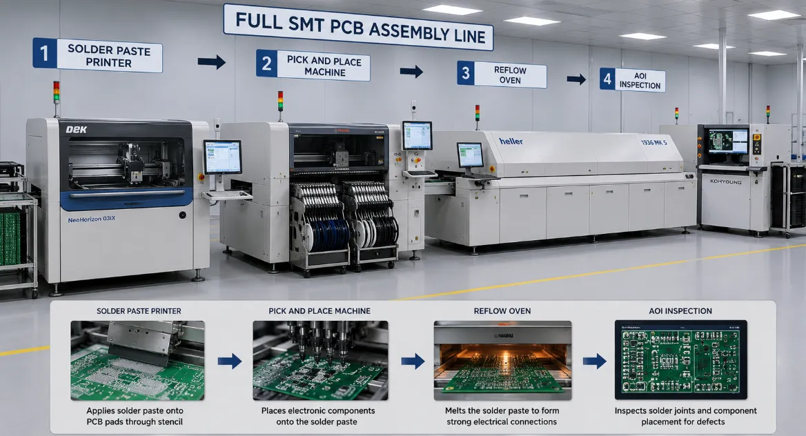
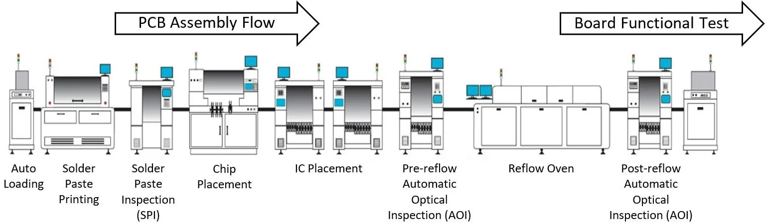
A standard pcb assembly equipment list includes machines tailored for SMT processes, from paste application to final inspection. Core components handle solder deposition, component mounting, reflow soldering, and quality checks. This setup supports both prototyping and high-volume manufacturing. Engineers often configure lines modularly to adapt to diverse board sizes and densities. Below, we detail the primary machines, their functions, and practical considerations.
Solder Paste Printer
The solder paste printer, also known as a stencil printer, applies solder paste precisely onto PCB pads through a metal stencil. Engineers align the stencil with fiducials using vision systems to achieve micron-level accuracy. Paste viscosity and stencil thickness influence deposit height, critical for preventing insufficient solder joints. Troubleshooting common issues like paste smearing involves adjusting squeegee pressure and speed, ensuring clean releases.
This machine sets the foundation for assembly success, as poor paste application amplifies downstream defects. Automatic printers feature closed-loop controls for consistent volume across panels. Regular maintenance, such as stencil cleaning cycles, extends equipment life and maintains yield rates. For electric engineers, integrating solder paste inspection (SPI) post-printing verifies deposit quality before placement.
Pick and Place Machine
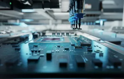
The pick and place machine, a high-speed robot, retrieves components from feeders and positions them onto paste-coated pads. Nozzles of varying sizes handle chips, QFPs, BGAs, and odd-form parts with sub-50-micron precision. Vision cameras correct offsets and rotations, essential for double-sided boards. Engineers optimize feeder setups and program heads to balance throughput and accuracy, often achieving 50,000+ components per hour on modular systems.
Feeder types, like tape, tray, or tube, affect changeover times in high-mix environments. Troubleshooting misalignment starts with calibration routines and nozzle condition checks. Software simulates placements to predict bottlenecks, aiding line balancing. This machine's flexibility makes it the heart of diverse production runs.
Related Reading: Pick and Place Machine Programming: A Beginner's Guide to SMT Automation
Reflow Oven
The reflow oven solders components by heating the board through controlled profiles: preheat, soak, reflow, and cooling zones. Convection heating ensures uniform temperatures across large panels, vital for lead-free alloys. Engineers profile ovens using thermocouples to match component tolerances, avoiding overheating sensitive parts. JEDEC J-STD-020 outlines reflow conditions to classify moisture sensitivity, preventing popcorn effects.
Zone configurations, typically 8-12, allow fine-tuning ramp rates and peak temperatures. Troubleshooting hot spots involves nitrogen atmospheres to reduce oxidation. Data from onboard sensors logs profiles for traceability and process verification. Proper exhaust management handles flux vapors, maintaining a safe shop floor.
Automated Optical Inspection (AOI)
Automated optical inspection (AOI) scans boards with cameras and lights to detect defects like missing parts, polarity errors, or solder bridges. Multi-angle imaging and 3D profiling provide comprehensive views, comparing against golden boards or CAD data. Engineers set tolerances for component presence, alignment, and joint fillet shapes per IPC-A-610 acceptability criteria. Post-reflow AOI catches issues early, boosting first-pass yields.
Programming involves teaching the system via sample boards, with AI enhancing defect classification over time. Troubleshooting false calls requires lighting adjustments and algorithm tweaks. Inline AOI integrates seamlessly, providing real-time feedback to upstream machines. For complex BGAs, combining with X-ray complements AOI's surface focus.
Related Reading: AOI machine programming method
Best Practices for Integrating PCB Assembly Equipment
Align machines on a single conveyor with standardized widths for smooth transfers. Engineers should map takt times to avoid bottlenecks, such as pick and place waiting on printing. Implement MES software for recipe management across the line, ensuring traceability from paste lot to final AOI results. Regular preventive maintenance, like vision system cleans and belt tensions, prevents unplanned stops.
Calibrate equipment weekly using gauge R&R studies for repeatability. For mixed THT/SMT, add selective soldering post-reflow. Nitrogen use in reflow and printers reduces voids, per J-STD-001 soldering guidelines. Simulate full runs to validate setups before production.
Troubleshooting Common PCB Assembly Challenges
Tombstoning often stems from uneven paste heights or rapid reflow ramps; adjust printer volumes and preheat soaks. Bridging in dense areas calls for finer stencils or paste with lower tackiness. Pick and place errors like skips trace to feeder jams or vacuum faults, resolved by sensor diagnostics. AOI flags excessive voids? Profile the reflow oven for better soak times.
Component shifts post-placement indicate insufficient tack; increase paste area or humidity controls. Warpage issues demand board supports in printers and ovens. Log data from all machines to correlate defects, enabling predictive fixes. Cross-training operators on error codes accelerates resolutions.
Conclusion
Mastering the pcb assembly equipment list empowers electric engineers to build robust production lines. From solder paste printer precision to AOI verification, each machine contributes to defect-free assemblies. Adhering to standards like IPC-A-610 ensures consistent quality across classes. Invest time in setup, calibration, and troubleshooting for optimal performance. This integrated approach drives efficiency, reliability, and innovation in electronics manufacturing.
FAQs
Q1: What is the typical sequence in a pcb assembly equipment list for SMT?
A1: The sequence starts with the solder paste printer for stencil application, followed by the pick and place machine for component mounting, then the reflow oven for soldering, and ends with automated optical inspection (AOI) for defect detection. This flow minimizes handling and maximizes inline corrections. Engineers adjust based on board complexity, ensuring conveyor compatibility. Proper sequencing prevents paste drying or shifts.
Q2: How does a pick and place machine handle high-mix production?
A2: Pick and place machines use modular heads and intelligent feeders to switch between component types quickly. Vision systems verify placements in real-time, reducing errors. Engineers program via CAD import for rapid setups. Troubleshooting feeder issues keeps changeovers under 30 minutes, ideal for prototyping.
Q3: Why is temperature profiling critical in reflow ovens?
A3: Reflow ovens require precise profiles to melt solder without damaging components. Preheat removes flux activators evenly, soak stabilizes temperatures, and peak reflow forms joints. Per JEDEC J-STD-020, profiles classify sensitivity levels. Engineers use dataloggers to troubleshoot voids or overheating.
Q4: What role does automated optical inspection (AOI) play in quality control?
A4: AOI detects visual defects like misalignments or insufficient solder post-reflow. It compares boards to reference images, flagging issues per IPC-A-610 criteria. Inline placement boosts yields by feeding back to pick and place. Engineers refine algorithms for fewer false positives.
References
IPC-A-610J — Acceptability of Electronic Assemblies. IPC, 2024
IPC J-STD-001H — Requirements for Soldered Electrical and Electronic Assemblies. IPC, 2020
JEDEC J-STD-020F — Moisture/Reflow Sensitivity Classification for Nonhermetic Surface Mount Devices. JEDEC, 2021


