 ALLPCB


Introduction
Light-emitting diodes have transformed lighting applications due to their superior energy efficiency and compact form factors compared to traditional sources. However, high-power and high-brightness LEDs generate significant heat during operation, which can degrade performance and shorten operational life if not managed properly. Metal core printed circuit boards, or MCPCBs, play a pivotal role in addressing these thermal challenges by providing enhanced heat dissipation pathways. This enables LEDs to maintain lower junction temperatures, directly contributing to improved efficiency and extended longevity. In demanding applications like street lighting, automotive headlights, and industrial fixtures, MCPCBs for LED efficiency become essential for reliable performance. Engineers designing LED systems must prioritize thermal management from the PCB level to optimize overall system reliability.
What Is an MCPCB and Why It Matters for LED Lighting
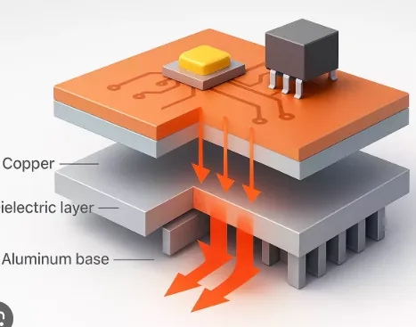
An MCPCB consists of a solid metal base, typically aluminum or copper, bonded to a thermally conductive dielectric layer and topped with a copper circuit layer. This construction differs from standard FR-4 PCBs, where a fiberglass-reinforced epoxy serves as the core with poor thermal conductivity. The metal core in MCPCBs efficiently spreads heat laterally and conducts it away from heat-generating components like LEDs. For LED applications, this structure is critical because LEDs are sensitive to elevated temperatures that reduce luminous efficacy and accelerate degradation mechanisms such as phosphor conversion loss.
The relevance of MCPCBs in LED lighting stems from the need to handle power densities exceeding those of conventional electronics. High-brightness LED PCB designs often operate at currents that produce junction temperatures above 100 degrees Celsius without proper cooling, leading to rapid droop in output and color shift. By integrating an MCPCB, designers achieve a lower thermal resistance path from the LED package to the ambient environment or heatsink. This not only boosts LED lifespan PCB reliability but also aligns with industry demands for sustainable, long-lasting lighting solutions. Factories producing MCPCBs emphasize consistent layer bonding to prevent delamination under thermal cycling, ensuring compliance with performance specifications.
Technical Principles of Thermal Management in MCPCBs
Heat generated in an LED originates at the p-n junction and must transfer through the package, solder joint, PCB, and ultimately to a heatsink or convection. MCPCBs excel here due to the high thermal conductivity of the metal core, which is orders of magnitude better than epoxy-based substrates. The dielectric layer, engineered with fillers like alumina or boron nitride, bridges the electrical insulation needs with acceptable thermal conductance, typically in the range that supports efficient heat flow without excessive voltage drop. Thermal vias filled with conductive paste further enhance vertical heat transfer from traces to the core, minimizing hotspots under high-brightness LEDs.
MCPCB thermal resistance is a key metric, representing the temperature rise per unit of power dissipated, and it directly influences LED efficiency. Lower thermal resistance allows the LED to operate closer to its optimal temperature, preserving forward voltage stability and photon output. Engineers model this using finite element analysis to predict temperature profiles across the board. Standards like IPC-2221 provide guidelines for trace widths and spacings that accommodate current carrying while supporting thermal paths. In high-density arrays, uniform heat spreading prevents thermal runaway in adjacent devices.
The coefficient of thermal expansion mismatch between the metal core and copper layers requires careful control during lamination to avoid warpage or cracking. Factory processes apply controlled pressure and temperature ramps to achieve void-free bonding. This ensures the MCPCB maintains structural integrity through assembly reflow cycles, as outlined in IPC-6012 performance specifications for rigid boards. Proper management of these principles results in LED systems that sustain high lumen maintenance over thousands of hours.
Related Reading: Solving Thermal Challenges in Power Electronics with MCPCBs: A Comprehensive Guide

LED PCB Design Best Practices Using MCPCBs
Effective LED PCB design begins with selecting the appropriate MCPCB stackup based on power requirements and environmental conditions. For high-brightness applications, a 1.5 mm thick aluminum core with a 100-150 micrometer dielectric offers balanced rigidity and thermal performance. Place LEDs symmetrically to promote even heat distribution, and position driver circuitry away from hotspots to avoid interference. Incorporate arrays of thermal vias under each LED pad, plated and back-drilled if necessary, to direct heat straight to the core without spreading laterally first.
Trace routing should prioritize wide copper pours under LEDs for lateral spreading, following IPC-2221 rules for current capacity to prevent electromigration. Solder mask openings must align precisely with thermal pads to maximize contact area during reflow soldering. Designers often specify white solder mask for better light reflection, enhancing optical efficiency in lighting modules. Testing prototypes for thermal resistance involves infrared imaging to validate models against real-world operation.
Assembly considerations include using low-temperature solders compatible with the dielectric to minimize stress. Post-assembly, conformal coatings protect against humidity, which can exacerbate corrosion in LED environments. Factories validate these designs through thermal cycling tests per JEDEC standards for component reliability. These practices ensure MCPCBs for LED efficiency translate into field-proven longevity.
Related Reading: Troubleshooting LED PCB Hotspots: Diagnosing and Preventing Thermal Failures
Challenges and Solutions in MCPCB Implementation for LEDs
One common challenge in high-brightness LED PCB is mechanical stress from CTE differences, leading to potential solder joint fatigue over time. Solutions involve embedding stress-relief features like slotted vias or flexible dielectric formulations. Another issue is edge effects where heat concentrates, addressed by oversized copper planes extending to board edges for better heatsink coupling.
Cost pressures sometimes tempt designers to thinner cores, but this compromises spreading capability, so balance with simulation data. Manufacturing tolerances in dielectric thickness directly impact thermal resistance, requiring tight process controls in production. Troubleshooting involves dissecting failed units to check for voids or delamination, then iterating stackups.
Conclusion
MCPCBs fundamentally advance LED lighting by providing superior thermal management that enhances efficiency and extends service life. Their layered construction, optimized for heat conduction, addresses the core limitations of standard PCBs in high-power scenarios. Adhering to best practices in design and manufacturing, guided by industry standards, ensures robust performance. Electric engineers benefit from integrating MCPCBs early in the process to meet stringent reliability targets. As lighting evolves toward higher densities, the role of these specialized boards will only grow.
FAQs
Q1: What makes MCPCB thermal resistance superior for LED applications?
A1: MCPCB thermal resistance benefits from the metal core’s high conductivity, which rapidly spreads heat from LED junctions compared to FR-4 substrates. The dielectric layer maintains insulation while allowing efficient vertical transfer via thermal vias. This setup keeps operating temperatures low, preserving luminous efficacy. Factory processes ensure consistent performance per IPC standards.
Q2: How does LED lifespan PCB improve with MCPCBs?
A2: MCPCBs extend LED lifespan PCB by minimizing junction temperature rises that accelerate degradation. Heat dissipation prevents color shifts and lumen depreciation over time. Designs with proper via placement and core thickness yield reliable longevity in high-brightness setups. Engineers model these effects to predict 50,000-hour operation.
Q3: What are key considerations in high-brightness LED PCB design using MCPCBs?
A3: High-brightness LED PCB design requires symmetric layouts, wide thermal pads, and arrays of filled vias for optimal heat flow. Select dielectric with adequate conductivity matching power levels. Comply with IPC-2221 for routing to handle currents without hotspots. Validate with thermal profiling for production scalability.
Q4: Why choose MCPCBs for LED efficiency in demanding environments?
A4: MCPCBs for LED efficiency excel in automotive or industrial settings due to robust heat handling under vibration and cycling. The aluminum core provides mechanical strength alongside thermal benefits. This combination supports higher drive currents for brighter output without efficiency loss. Standards like JEDEC guide reliability testing.
References
IPC-2221B — Generic Standard on Printed Board Design. IPC, 2012
IPC-6012E — Qualification and Performance Specification for Rigid Printed Boards. IPC, 2017
JEDEC JESD51-51 — Implementation of the Electrical Test Standard for LED Packages. JEDEC, 2012


