ALLPCB


Introduction
Assembling your first batch of PCBs marks a thrilling milestone in any electronics hobbyist's journey. This PCB assembly tutorial transforms bare boards into functional circuits, bringing your designs to life through hands-on soldering and testing. As a beginner's guide to electronics, it emphasizes visual cues and simple steps to build confidence. Whether you have five or fifty boards, following a structured process ensures reliable results without common pitfalls. This visual guide to soldering breaks down each phase, helping you avoid frustration and achieve professional-looking assemblies. Get ready to equip your workbench and dive into the practical world of step-by-step assembly.
Why PCB Assembly Matters for Hobbyists
PCB assembly bridges the gap between schematic dreams and working prototypes, empowering hobbyists to create custom projects like LED drivers or sensor modules. Unlike breadboards, soldered PCBs offer compact, durable, and vibration-resistant electronics suitable for enclosures or wearables. Mastering this skill saves time and money compared to outsourcing small batches, while fostering troubleshooting expertise. Industry standards like IPC-A-610J provide clear benchmarks for joint quality, ensuring your hobby projects meet basic reliability thresholds. For electronic hobbyists, this process builds intuition for component behavior and solder flow, accelerating future PCB project guides. Ultimately, it turns passive learners into active creators who iterate designs with precision.
Essential Tools and Materials for PCB Assembly
Before starting your PCB assembly tutorial, gather tools that support clean, efficient work. A temperature-controlled soldering iron, fine-tip solder wire with rosin core, flux pen, tweezers, and flush cutters form the core kit. Add a magnifying glass or visor, helping hands tool, isopropyl alcohol for cleaning, and a multimeter for verification. Desoldering wick or a pump handles mistakes, while anti-static mats protect sensitive components. Organize everything on a well-lit, stable surface to minimize movement during soldering. This setup aligns with best practices in a visual guide to soldering, preventing contamination and ensuring steady hands.
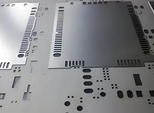
For your first batch, sort components by value and package type using labeled trays. Verify quantities against your bill of materials to avoid shortages mid-process. Inspect PCBs for warpage, burrs, or plating defects under bright light. Components should have clear markings and no bent leads. Prepping thoroughly prevents rework, a key troubleshooting tip for beginners. Proper material handling sets the foundation for a smooth step-by-step assembly.
Preparing Your PCBs and Components
Visual inspection kicks off any reliable PCB project guide. Hold each board to light, checking for scratches, missing pads, or silkscreen errors from fabrication. Measure board thickness and flatness if possible, as excessive warpage can complicate soldering. Sort components, straightening leads on resistors and capacitors with pliers. For surface-mount devices, ensure no tombstoning risks from mismatched sizes. This phase, guided by standards like IPC J-STD-001J, catches issues early, saving hours later.
Apply flux sparingly to pads and leads for better solder wetting, especially on oxidized surfaces. For through-hole parts, pre-tin leads by melting a thin solder coat. Avoid excess flux to prevent bridging during a visual guide to soldering. Bend leads to fit holes snugly but not stressing the board. Preheat the oven or use a hot air station only for reflow if attempting SMD. Preparation directly impacts joint integrity per industry criteria.
Step-by-Step Through-Hole Soldering Process
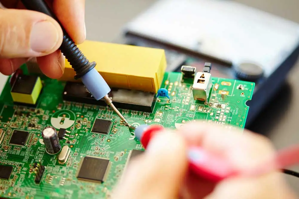
Begin your beginner's guide to electronics with through-hole components, soldering low-profile ones first to avoid clearance issues. Insert parts from the top side, bending leads outward in a V-shape to secure them. This step-by-step assembly keeps components stable without tape. Heat the pad and lead simultaneously for two to three seconds, then feed solder until it flows evenly around the joint. A shiny, concave fillet indicates success, matching IPC-A-610J acceptability class 2 for hobby use. Withdraw heat promptly to prevent overheating delicate parts.
Progress systematically: populate one row or section at a time, checking polarity on diodes and ICs. Solder resistors and capacitors before taller parts like connectors. Clip excess leads close to the joint with flush cutters, angling the cut to avoid flying shards. Rotate the board to minimize awkward angles, a practical tip in any PCB assembly tutorial. If bridges form, use wick and flux to clean precisely. Consistent technique yields uniform results across your batch.
For dual-sided boards, complete one side fully before flipping. This prevents disturbing unset joints. Test continuity between pins as you go with a multimeter in beep mode. Address opens or shorts immediately for efficient troubleshooting. Visual inspection post-soldering reveals cold joints, which appear dull and reheat easily.
Handling Surface-Mount Components for Beginners
Surface-mount soldering suits simple hobby projects with resistors, capacitors, and basic ICs. Use a fine-tip iron and low-melt solder for 0805 or larger packages. Apply flux to pads, place parts with tweezers, and tack one end by heating the pad edge. Align precisely, then solder the other side, avoiding direct component heat. This visual guide to soldering prevents tombstoning, where uneven heating lifts one end.
Drag-solder longer rows by coating with flux and running the iron tip along leads. Inspect for voids or excess using magnification. For QFNs or SOICs, ensure exposed pads get proper heat via thermal relief. Practice on scrap boards to build speed and accuracy. Standards like IPC J-STD-001J emphasize fillet formation even for SMD, guiding hobbyist quality.
Post-Assembly Inspection and Cleaning
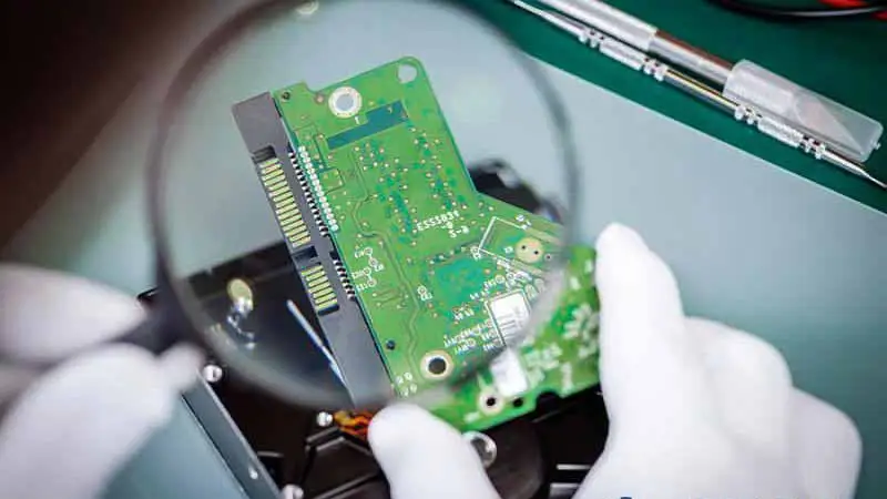
Scrutinize every joint against IPC-A-610J criteria: smooth barrel fill, no cracks, and proper wetting. Class 2 allows minor imperfections for non-critical hobby circuits. Use a bright light and magnifier to spot bridges or dewetting. Probe with a meter for shorts between adjacent pads. This troubleshooting-focused check catches 90% of issues before power-up.
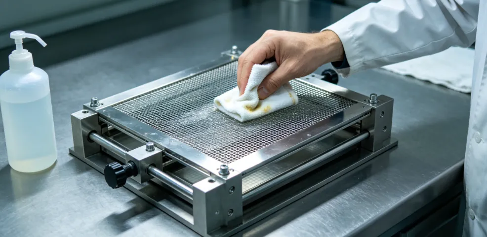
Clean flux residues with isopropyl alcohol and a soft brush, as activators can corrode over time. Rinse multiple times and dry thoroughly with compressed air. Avoid soaking sealed components. A residue-free board ensures long-term reliability in your PCB project guide.
Functional Testing and Troubleshooting
Power up gradually: check voltages first without load, then add peripherals. Use a bench supply limited to safe currents. Monitor for heat spots with a temperature sticker or finger test after seconds. Debug opens by rechecking orientations, shorts via visual and meter confirmation.
Common fixes include reflowing cold joints or desoldering bad parts. Wick away excess solder carefully. For batch consistency, log defects per board to refine future runs. This iterative approach hones skills in a beginner's guide to electronics.
Conclusion
This PCB assembly tutorial equips you with a visual guide to soldering your first batch successfully. From prep to testing, each step builds reliable hobby circuits while referencing key standards like IPC-A-610J and IPC J-STD-001J. Troubleshooting early prevents cascading errors, ensuring satisfaction in every powered prototype. Scale up confidently to complex designs, iterating with gained insights. Embrace the hands-on process, and watch your electronics projects flourish.
FAQs
Q1: What does a basic PCB assembly tutorial cover for beginners?
A1: A PCB assembly tutorial starts with tool setup, PCB inspection, component placement, and hand soldering techniques. It emphasizes visual checks for joint quality per IPC-A-610J and cleaning steps. Testing continuity and power-up verification follow, with troubleshooting for common issues like bridges or cold joints. This step-by-step assembly builds foundational skills safely for hobbyists.
Q2: How can a visual guide to soldering improve my results?
A2: A visual guide to soldering shows proper heat application, solder flow, and fillet shapes, reducing defects like dewetting. It highlights flux use and lead trimming for clean work. Beginners match their joints to example images, aligning with J-STD-001J requirements. Practice accelerates proficiency across batches.
Q3: Why include inspection in a beginner's guide to electronics assembly?
A3: Inspection verifies pad integrity and component fit before soldering, catching fab errors early. Post-solder checks per IPC standards ensure reliability. It teaches spotting issues like insufficient fill, preventing field failures. This practical step saves time in PCB project guides.
Q4: What troubleshooting tips apply to step-by-step PCB assembly?
A4: Identify dull joints for reflow, bridges for wick removal, and polarity errors via meter tests. Clean flux to avoid corrosion. Batch-log defects for process tweaks. These fixes maintain consistency without advanced tools.
References
IPC-A-610J — Acceptability of Electronic Assemblies. IPC, 2024
IPC J-STD-001J — Requirements for Soldered Electrical and Electronic Assemblies. IPC, 2024