 ALLPCB


Introduction
Printed circuit board assemblies (PCBAs) form the backbone of modern electronics, where reliability directly impacts system performance and longevity. In demanding applications ranging from consumer devices to aerospace systems, even minor defects in soldering or component placement can lead to catastrophic failures. IPC standards offer a rigorous framework to evaluate and ensure PCBA IPC-A-610 reliability, providing clear criteria for acceptability and performance. This comprehensive guide explores key IPC class standards and testing protocols like PCBA IPC-9701 testing, helping electric engineers decode these essentials for robust designs. By aligning with PCBA IPC standards for reliability testing, manufacturers can minimize field failures and optimize production processes. Understanding these standards empowers engineers to make informed decisions throughout the design, assembly, and qualification phases.
Understanding PCBA Reliability and Its Critical Role
PCBA reliability refers to the ability of an assembled board to perform consistently under specified operating conditions over its intended lifespan. Factors such as thermal cycling, mechanical stress, and environmental exposure challenge solder joints and interconnections, potentially causing cracks or delamination. Without standardized benchmarks, assessing reliability becomes subjective, leading to inconsistent quality across suppliers. IPC class standards categorize assemblies into levels that match end-use requirements, ensuring that general consumer products differ from high-stakes mission-critical systems. For electric engineers, grasping PCBA IPC class standards means selecting the appropriate rigor during procurement and validation. Ultimately, prioritizing reliability reduces warranty claims and enhances product reputation in competitive markets.
High reliability matters because failures in PCBAs often manifest after deployment, amplifying costs through recalls or downtime. In sectors like telecommunications or automotive, a single assembly defect can cascade into system-wide issues. Standards like those from IPC bridge the gap between design intent and manufacturing reality by defining visual and functional acceptance criteria. Engineers must consider how assembly processes influence long-term durability, from solder fillet formation to component alignment. By integrating these guidelines early, teams avoid costly rework and accelerate time-to-market. This structured approach fosters confidence in PCBA performance across diverse applications.
IPC Class Standards: Defining Quality Levels for PCBA
IPC class standards divide electronic assemblies into three tiers based on reliability needs and end-use environments. Class 1 applies to general electronic products where occasional failures are tolerable, such as toys or basic appliances, focusing on basic functionality without stringent inspection. Class 2 targets dedicated service electronics, like computers or office equipment, demanding higher consistency for uninterrupted operation over years. Class 3 sets the highest bar for high-reliability products in aerospace, medical devices, or military gear, where zero defects are essential due to safety and mission implications.
Each class in PCBA IPC class standards imposes progressively tighter criteria on solder joints, cleanliness, and markings. For instance, Class 3 prohibits certain voids or misalignments allowed in lower classes, reflecting the need for superior fatigue resistance. Engineers select a class during design to guide fabrication and assembly tolerances. Misaligning class with application risks over-engineering low-end products or under-specifying critical ones. Visual aids in the standards illustrate acceptable versus defective conditions, aiding inspectors in consistent evaluations. Adopting the right class ensures PCBA IPC-A-610 reliability aligns with operational demands.
Differences across classes become evident in areas like lead coplanarity and hole fill percentages. Class 1 permits greater deviations, suiting cost-sensitive volumes, while Class 3 requires near-perfect conformance to withstand vibration and temperature extremes. Troubleshooting starts with class specification in contracts to prevent disputes. Engineers often use tables comparing criteria for quick reference during reviews. This tiered system promotes efficiency without compromising safety where needed.
PCBA IPC-A-610 Reliability: Visual Acceptability Criteria
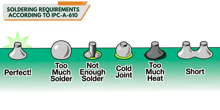
IPC-A-610 establishes detailed visual inspection standards for electronic assemblies, directly tying workmanship to PCBA IPC-A-610 reliability. It covers soldering anomalies, component placement, and cleanliness, with criteria scaled by class. Solder joints must exhibit proper wetting and fillet shapes to ensure mechanical strength and electrical continuity. Defects like bridging or insufficient solder volume signal potential early failures under stress. Inspectors use magnification and lighting to verify conformance, focusing on high-risk areas such as ball grid arrays or fine-pitch components.
The standard addresses hardware installation, ensuring leads do not protrude hazardously and adhesives cure properly. For PCBA IPC-A-610 reliability, criteria extend to conformal coatings, which protect against moisture and contaminants. Engineers troubleshoot by cross-referencing photos in the document against actual boards. Common issues include cold joints, identifiable by dull appearances, versus shiny acceptable ones. Regular training on updates maintains inspector proficiency. Compliance verifies that assemblies withstand handling and initial stresses before advanced testing.
Beyond soldering, IPC-A-610 evaluates laminate conditions and markings legibility, preventing traceability losses. High-reliability classes demand void-free soldermask and no delamination signs. Practical application involves automated optical inspection calibrated to standard thresholds. Deviations prompt root-cause analysis, often tracing to reflow profiles or stencil misalignment. Integrating these checks into production lines boosts yield and reliability.
PCBA IPC-9701 Testing: Qualifying Solder Joint Durability
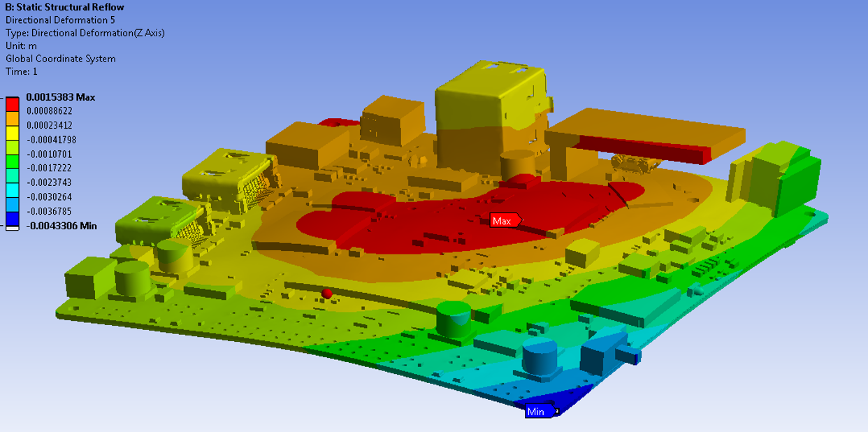
PCBA IPC-9701 testing provides performance qualification for surface mount solder attachments through accelerated stress methods. It outlines thermal cycling protocols to simulate field aging, revealing fatigue weaknesses in joints. Test assemblies undergo repeated temperature ramps, monitoring resistance for opens or increased values indicating cracks. Conditions vary by severity, matching product classes and environments. Engineers analyze failure data using statistical models to predict lifespan.
The standard specifies daisy-chain monitoring for efficient detection across multiple joints. Qualification passes when assemblies exceed characteristic life metrics under defined dwells and ramps. This testing complements visual IPC-A-610 checks by validating long-term behavior. Troubleshooting failures involves sectioning joints for microscopy, identifying intermetallic growth or void propagation. Implementing PCBA IPC-9701 testing early in new designs de-risks transitions like lead-free soldering.

Additional stresses like vibration or humidity can integrate into protocols for holistic assessment. Data logging at intervals captures degradation trends. Engineers correlate test outcomes with field data for refinement. This methodical approach ensures PCBA IPC standards for reliability testing deliver proven durability.
Best Practices for Implementing IPC Standards in PCBA Production
Select the appropriate IPC class upfront based on failure tolerance and environment to guide all processes. Collaborate with assemblers certified in relevant standards for consistent execution. Establish incoming inspections using IPC-A-610 checklists to catch defects early. Automate where possible, but retain manual verification for Class 3 nuances.
Incorporate PCBA IPC-9701 testing during process validation, especially after material changes. Document deviations with engineering justifications, avoiding blanket waivers. Train teams on standard illustrations for uniform interpretation. Monitor process indices like first-pass yield tied to criteria.
Maintain traceability through serialized boards and test reports. Periodic audits ensure ongoing compliance. These practices elevate PCBA IPC standards for reliability testing into production realities.
Troubleshooting Common PCBA Reliability Issues Using IPC Guidelines
Solder bridges often arise from excessive paste volume; IPC-A-610 classes define cleanup thresholds. Tombstoning in reflow signals paste imbalance, resolvable by stencil adjustments. Head-in-pillow defects mimic good joints visually but fail electrically, demanding profile tweaks.
Cracking post-testing per IPC-9701 points to brittle intermetallics; mitigate with alloy selection. Delamination under humidity tests requires bake-outs. Cross-section analysis confirms root causes against standard photos.
Field returns guide process refinements, looping back to class criteria.
Conclusion
IPC standards demystify PCBA reliability, offering electric engineers actionable frameworks from visual checks to endurance testing. PCBA IPC class standards tailor quality to needs, while IPC-A-610 and IPC-9701 ensure workmanship and durability. Integrating these minimizes risks and maximizes performance. Prioritize them for resilient assemblies that excel in real-world stresses.
FAQs
Q1: What distinguishes PCBA IPC class standards for different applications?
A1: PCBA IPC class standards define Class 1 for basic consumer goods with lenient criteria, Class 2 for reliable commercial use requiring consistent performance, and Class 3 for critical systems demanding defect-free assemblies. Engineers choose based on downtime tolerance and environment. This ensures PCBA IPC-A-610 reliability matches operational risks without excess cost.
Q2: How does PCBA IPC-9701 testing evaluate solder joint reliability?
A2: PCBA IPC-9701 testing uses thermal cycling to accelerate fatigue, monitoring electrical continuity in daisy-chained joints. Assemblies endure ramp-dwell cycles until characteristic life metrics. Failures trigger analysis for process improvements. It qualifies surface mount attachments for long-term PCBA IPC standards for reliability testing.
Q3: Why is IPC-A-610 essential for PCBA IPC-A-610 reliability?
A3: IPC-A-610 provides visual criteria for soldering, placement, and cleanliness, scaled by class to predict reliability. It catches workmanship issues before field deployment. Regular inspections per this standard reduce escapes in high-volume production.
Q4: How do engineers apply PCBA IPC standards for reliability testing in design?
A4: Engineers specify classes and tests like IPC-9701 upfront, influencing layout and materials. They validate prototypes against criteria, iterating as needed. This proactive use of PCBA IPC standards for reliability testing bridges design and manufacturing for robust outcomes.
References
IPC-A-610H — Acceptability of Electronic Assemblies. IPC, 2020
IPC-9701B — Performance Test Methods and Qualification Requirements for Surface Mount Solder Attachments. IPC, 2022


