 ALLPCB


Introduction
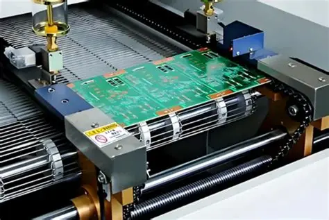
In surface mount technology assembly lines, pick and place machines form the backbone of production efficiency, rapidly positioning thousands of components onto printed circuit boards. Feeders play a pivotal role by delivering components precisely and reliably to the placement heads, directly influencing overall throughput measured in components per hour. Optimizing feeder configuration addresses common bottlenecks such as jams, misfeeds, and excessive head travel, enabling engineers to achieve higher speeds without sacrificing accuracy. This practical guide draws on established engineering principles to help troubleshoot and enhance feeder performance in real-world SMT environments. By focusing on feeder types, calibration, and strategic placement, manufacturers can significantly boost machine utilization.
Understanding Feeder Types in SMT Pick and Place Systems
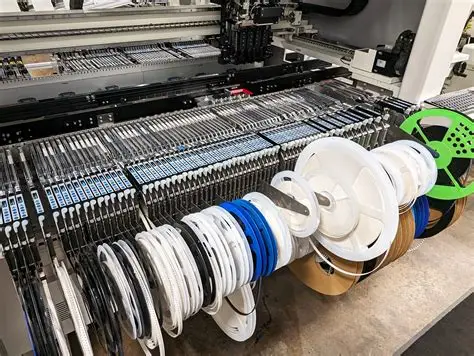
Feeders in SMT pick and place machines are specialized devices designed to handle various component packaging formats, each suited to specific part sizes and production volumes. Tape feeders dominate due to their compatibility with reel-mounted surface mount devices, advancing embossed or paper tape to expose components for pickup. Tray feeders accommodate matrix trays for larger integrated circuits or odd-form parts, while tube and stick feeders manage bulk or radial components through vibration or gravity. Selecting the appropriate feeder type ensures seamless integration with the machine's nozzle system and minimizes changeover times during high-mix runs. Engineers must evaluate component pitch, width, and quantity to match feeder capabilities, as mismatches often lead to placement errors or reduced speeds.
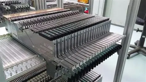
Tape feeders, in particular, require precise motor control to index tape at rates synchronized with the placement head's cycle time. Pneumatic variants use air pressure for peeling, while motorized ones offer finer speed adjustments for delicate components. Tray feeders typically feature matrix positioning with vacuum or mechanical grippers, ideal for JEDEC trays in high-precision applications. Troubleshooting starts with verifying feeder compatibility against the bill of materials, as incorrect types can halve throughput by forcing manual interventions.
Why Feeder Optimization Matters for Throughput
Feeder inefficiencies manifest as the primary limiter in maximizing pick and place speed, often capping performance well below machine specifications. Excessive head travel to distant feeders, frequent nozzle swaps, or inconsistent feeding interrupts the placement rhythm, dropping components per hour dramatically. In high-volume production, even minor delays compound into hours of lost output, inflating costs and straining deadlines. Proper pick and place feeder optimization aligns feeder setup with job requirements, reducing cycle times by streamlining pick sequences and minimizing errors. For electrical engineers, this means correlating feeder performance metrics like feed pitch accuracy with final assembly yields.
Adherence to standards such as IPC-9850A ensures that feeder contributions to overall placement accuracy are quantifiable and optimized. This standard outlines characterization methods for surface mount placement equipment, including feeder reliability under load. Beyond speed, optimized feeders enhance repeatability, critical for maintaining tolerances in dense board layouts. Neglecting this step risks tombstoning or bridging in reflow, traceable back to inconsistent component presentation.
Key Technical Principles of Feeder Operation
The core mechanism of a tape feeder involves sequential tape advancement, cover tape peeling, and component exposure at the fixed pick position, all calibrated to the machine's vacuum nozzle descent. Pitch errors greater than 0.1 mm disrupt pickup, causing skips or doubles that halt production. Peeling force must balance tape integrity with component release, adjustable via tension springs or software parameters. For multi-head machines, feeders must sustain high indexing rates without backlash, achieved through stepper motors or servo drives. Understanding these dynamics allows engineers to diagnose issues like tape jamming from cover tape adhesion or dust accumulation.
Feeder speed profiles must match the placement head's acceleration curves to avoid wait states, where the head idles for the next component. Vision-assisted systems verify pick height and orientation post-feed, flagging deviations for immediate correction. Tray and tube feeders introduce variability through pocket alignment or vibration amplitude, requiring periodic leveling checks. IPC-A-610 provides criteria for acceptable component offsets post-placement, linking feeder precision directly to assembly quality. These principles underscore the need for holistic system tuning rather than isolated feeder tweaks.
Related Reading: Tape Feeders vs. Tray Feeders: Which is Best for Your SMT Assembly Line?
Practical Best Practices for Pick and Place Feeder Optimization
Begin feeder setup by mapping component usage frequency from the bill of materials, positioning high-volume feeders nearest the head's home or vision station to cut travel distances. Implement feeder placement strategies that cluster similar nozzle-required parts, reducing changeover frequency by up to 30 percent in optimized layouts. Load tapes with consistent tension, splicing ends properly to prevent gaps during long runs. Run dry cycles to validate feed pitch against programmed values, adjusting offsets via machine software.
Tape feeder calibration demands a dedicated jig to measure pick position relative to machine zero, ensuring Z-height contacts components without crushing pockets. Calibrate peel force iteratively, starting low to avoid tape tears, and verify with test picks under production speeds. Schedule weekly maintenance: clean sprockets, inspect clutches, and lubricate as needed to preempt wear. For tray feeders, align matrix pockets using fiducials and test vacuum hold-down. These steps in pick and place feeder optimization directly translate to sustained high throughput.
Software tools within modern machines auto-optimize sequences by minimizing total path length, factoring in feeder locations and rotations. Manually override for custom boards, prioritizing edge components to balance board warp during placement. Monitor feeder uptime via error logs, correlating faults with tape quality or environmental factors like humidity.
Related Reading: Choosing the Right Component Feeder: A Comprehensive Guide for SMT Assembly
Troubleshooting Common Feeder Issues
Feeder jams top the list of downtime culprits, often stemming from misaligned tape paths or worn sprockets that skip pitches. Inspect for debris in the peel mechanism and realign cover tape guides, then test with slow feeds. Mis-picks signal height mismatches; recalibrate Z-offset using a known-good component and vision feedback. For intermittent failures, check motor torque settings against feeder specs, as underpowered drives falter at max speed.
Tube feeders may vibrate excessively, dislodging parts; dampen with adjustable amplitude controls and secure tubes vertically. Tray misalignment causes grid skips, resolved by re-leveling the tray stack and verifying pocket depth. In high-speed runs, overheating grips indicate overload; cycle cool-downs or upgrade to intelligent feeders with error detection. Log incidents to pattern root causes, applying fixes proactively.
Persistent issues warrant full system audits per IPC-9850A protocols, benchmarking against baseline performance. This data-driven approach prevents recurrence, sustaining optimized throughput.
Conclusion
Mastering pick and place feeder optimization transforms assembly lines from bottleneck-prone setups to high-efficiency powerhouses. By selecting appropriate feeder types SMT, executing precise tape feeder calibration, and deploying smart feeder placement strategies, engineers unlock true maximizing pick and place speed potential. Regular troubleshooting and adherence to standards ensure long-term reliability. Implement these practices iteratively, measuring gains in components per hour, to elevate production without added hardware. The payoff lies in fewer defects, shorter cycles, and scalable output.
FAQs
Q1: What are the main feeder types SMT used in pick and place machines?
A1: Tape feeders handle reel components via indexed advancement, tray feeders manage JEDEC trays for ICs, tube feeders suit axial parts with gravity feed, and stick feeders vibrate radial components. Choose based on packaging and volume for optimal flow. Troubleshoot mismatches early to avoid throughput drops. This selection directly impacts pick and place feeder optimization efforts.
Q2: How does tape feeder calibration improve pick and place speed?
A2: Calibration aligns pick position, Z-height, and peel force using jigs, preventing mis-picks and jams that slow cycles. Verify pitch accuracy to match machine parameters, reducing head wait times. Perform quarterly with test tapes for consistency. This step in pick and place feeder optimization boosts reliability under high speeds.
Q3: What feeder placement strategies maximize pick and place machine throughput?
A3: Position frequent components centrally near vision or drop stations to minimize travel, group by nozzle type to cut changes, and sequence picks logically via software. Balance left-right for multi-head efficiency. Test layouts with simulations. These strategies enhance overall maximizing pick and place speed.
Q4: How can engineers troubleshoot feeder jams in SMT assembly?
A4: Check tape alignment, clean sprockets, verify tension, and inspect for wear. Slow-feed test to isolate pitch errors, then recalibrate. Monitor humidity to prevent static. Proactive logs prevent repeats, supporting sustained pick and place feeder optimization.
References
IPC-9850A — Surface Mount Placement Equipment Characterization. IPC, 2011
IPC-A-610J — Acceptability of Electronic Assemblies. IPC, 2024


