 ALLPCB


Introduction
Lead-free solder has transformed PCB assembly processes since the enforcement of RoHS directives, requiring engineers to rethink component selection entirely. Traditional tin-lead solders offered lower melting points and easier processing, but their replacement with alloys like SAC305 demands components that endure higher thermal stresses during reflow. This shift impacts lead-free component compatibility, forcing designers to prioritize parts with robust terminations and finishes suited for elevated temperatures. RoHS compliance adds layers of scrutiny, as non-conforming components can lead to assembly failures, reliability issues, or regulatory violations. In this article, we explore design considerations that ensure seamless integration of high-temperature components for lead-free solder, while addressing derating needs and finish options. Electrical engineers must balance performance, cost, and longevity when navigating these challenges.
Understanding Lead-Free Solder and RoHS Compliance
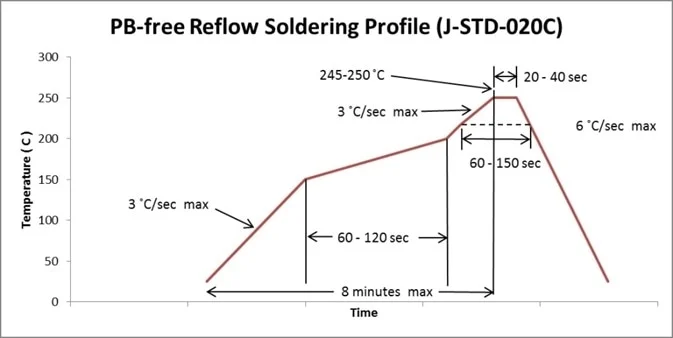
Lead-free solder primarily consists of tin-silver-copper alloys, which melt at higher temperatures compared to legacy tin-lead mixes, typically requiring peak reflow profiles up to 260 degrees Celsius. RoHS compliance mandates the elimination of lead and other hazardous substances, compelling the electronics industry to standardize on these higher-temperature processes. This change affects every stage of PCB assembly, from stencil printing to final inspection, as components must withstand prolonged exposure to heat without degrading. Engineers often overlook how this impacts lead-free component finishes, such as matte tin or gold plating, which prevent issues like solderability loss or intermetallic compound formation. J-STD-020 outlines moisture sensitivity levels that become critical here, as higher reflow times increase vapor pressure risks in plastic packages. Ultimately, RoHS component selection hinges on verifying that all parts align with these thermal demands to avoid defects like tombstoning or head-in-pillow.
Key Challenges in Lead-Free Component Compatibility
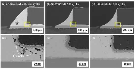
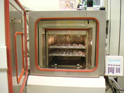
Lead-free component compatibility arises from the mismatch between traditional component ratings and the aggressive reflow profiles of lead-free solders. Many older components, designed for 183-degree Celsius peaks, suffer microcracks or delamination when exposed to 240-degree Celsius or higher. This necessitates a thorough review of datasheets for thermal endurance, focusing on maximum reflow classifications. High-temperature components for lead-free solder must feature reinforced molds and leads that resist warpage, ensuring joint integrity post-assembly. Troubleshooting often reveals failures from incompatible finishes, where bright tin plating leads to excessive intermetallics, compromising long-term reliability. Practical testing, such as thermal cycling per IPC-9701, helps identify these vulnerabilities early in the design phase.
Component derating plays a pivotal role, as lead-free processes induce higher stresses that reduce operational margins. Engineers apply derating factors to voltage, current, and temperature specs, often by 20 to 50 percent depending on the part family. For instance, capacitors and resistors may require larger footprints to dissipate heat effectively. Lead-free solder component derating also accounts for tin whisker growth on certain finishes, prompting selections of alloyed platings. Ignoring these factors results in field failures, such as increased leakage currents or intermittent opens. By integrating derating into simulations, teams can predict performance under real-world conditions.
Evaluating Lead-Free Component Finishes
Lead-free component finishes directly influence solder joint quality and RoHS compliance, with options like matte tin, pure tin over nickel, or ENIG providing varied benefits. Matte tin offers excellent wettability but requires controls to mitigate whisker risks through alloying or annealing. Pure tin finishes, while cost-effective, demand baking prior to reflow to prevent popcorning from absorbed moisture. Engineers must specify finishes compatible with SAC solders to minimize brittle intermetallics, which form faster at higher temperatures. JEDEC guidelines emphasize finish thickness uniformity, typically 3 to 15 micrometers, to ensure consistent barrel fill in vias and pads. Troubleshooting finish-related issues involves X-ray inspection for voids and shear testing for joint strength.
Selecting the right finish involves trade-offs between solderability, shelf life, and corrosion resistance. Gold over nickel excels in fine-pitch components but increases costs and risks black pad formation if nickel diffusion occurs. In high-reliability applications, pure gold is avoided due to its softness, leading to creep under thermal cycling. Practical advice centers on vendor qualification, requesting finish verification reports aligned with IPC standards. This ensures lead-free component finishes withstand multiple reflows without degradation, a common pain point in double-sided assemblies.
High-Temperature Components for Lead-Free Solder: Selection Criteria
High-temperature components for lead-free solder feature enhanced encapsulants and leadframes that tolerate peak temperatures exceeding 260 degrees Celsius for 30 seconds or more. Ceramic packages and high-Tg epoxies dominate where plastics falter, reducing risks of package crack during cooling ramps. Engineers prioritize MSL1 or MSL2 ratings per J-STD-020, as higher levels necessitate dry storage and floor life tracking. Component datasheets must explicitly state lead-free process compatibility, including preconditioning simulations. Derating curves become essential, plotting safe operating areas under elevated junction temperatures induced by reflow.
Passive components like MLCCs pose unique challenges, as lead-free reflow exacerbates piezoelectric cracking from board flexure. Selectors opt for softer dielectrics or base-metal electrode types with higher flex crack resistance. For actives like ICs, QFN and BGA packages require underfill to counter CTE mismatches amplified by lead-free solders. Troubleshooting involves acoustic microscopy to detect delams post-assembly. RoHS component selection thus demands a matrix approach, cross-referencing thermal, mechanical, and electrical specs.
Lead-Free Solder Component Derating Strategies
Lead-free solder component derating mitigates the accelerated aging from higher process temperatures and slower cooling rates. Standard practice applies factors from IPC-9701, reducing max ratings based on mission profiles like automotive or telecom. For power devices, derate current by 15 to 25 percent to limit self-heating during reflow transients. Voltage derating for passives prevents dielectric breakdown under thermal expansion stresses. Engineers model these using FEA tools, simulating stress distributions in solder joints.
Practical derating tables guide procurement, categorizing parts by family and environment. Inductors may need 30 percent power derating in dense layouts due to magnetic field interactions at high temps. Troubleshooting derating failures reveals patterns like electromigration in fine-pitch leads, addressed by wider traces. Integrating derating early optimizes board real estate while enhancing MTBF. This systematic approach ensures RoHS-compliant designs meet field durability.
Best Practices for RoHS Component Selection
Start RoHS component selection with a bill-of-materials audit, flagging legacy tin-lead parts for lead-free equivalents. Collaborate with suppliers for RoHS declarations and process capability data, verifying reflow profiles match your oven settings. Implement design rules like larger land patterns per IPC-7351 to accommodate volume expansion in SAC solders. Pre-bake MSL3+ components and monitor humidity to avert popcorn effects. For mixed assemblies, segregate zones to minimize thermal gradients.
Assembly trials validate selections, using profilometers to confirm peak temps and times. Post-reflow shear and thermal cycle tests per IPC-9701 quantify joint robustness. Document derating rationales in design reviews for traceability. These practices troubleshoot lead-free pitfalls proactively, ensuring high yields. Visual inspections catch finish anomalies like dewetting early.
Conclusion
Navigating lead-free solder's impact demands meticulous attention to component selection, from finishes to derating. High-temperature components for lead-free solder, paired with compatible terminations, form the backbone of reliable RoHS-compliant assemblies. Engineers who master lead-free component compatibility avoid costly respins and enhance product longevity. By leveraging standards like J-STD-020 and IPC-9701, teams achieve robust designs that withstand real-world stresses. Prioritize practical verification and proactive troubleshooting for optimal outcomes in PCB assembly.
FAQs
Q1: What factors determine lead-free component compatibility during reflow?
A1: Lead-free component compatibility hinges on thermal ratings, MSL classification per J-STD-020, and termination finishes like matte tin. Components must endure 260 degrees Celsius peaks without package deformation or moisture-induced cracks. Verify datasheets for lead-free process approvals and apply derating for safety margins. Troubleshooting focuses on void analysis and joint strength testing post-assembly.
Q2: How do high-temperature components for lead-free solder differ from standard parts?
A2: High-temperature components for lead-free solder use reinforced plastics, high-Tg materials, and robust leadframes to handle extended 240 to 260 degrees Celsius exposure. They feature lower moisture absorption and higher mechanical strength against warpage. Select based on reflow profile simulations and preconditioning per industry standards. This ensures reliability in dense, multi-layer boards.
Q3: Why is lead-free component derating necessary in RoHS designs?
A3: Lead-free solder component derating compensates for higher thermal stresses and slower cooling, which accelerate fatigue in joints and packages. Apply 20 to 50 percent reductions to ratings per IPC-9701 guidelines, tailored to operating environments. This prevents failures like cracking in MLCCs or electromigration in ICs. Model derating to balance performance and board space.
Q4: What are common lead-free component finishes for RoHS compliance?
A4: Lead-free component finishes include matte tin for wettability, ENIG for corrosion resistance, and alloyed tin to suppress whiskers. Thickness uniformity, 3 to 15 micrometers, ensures barrel fill and intermetallic control. Avoid pure tin without baking to prevent popcorning. Qualify finishes through solderability tests for consistent assembly yields.
References
J-STD-020E — Moisture/Reflow Sensitivity Classification for Nonhermetic Surface Mount Devices. JEDEC, 2014
IPC-9701 — Performance Test Methods and Qualification Requirements for Surface Mount Solder Attachments. IPC, 2017
IPC-7351D — Generic Requirements for Surface Mount Design and Land Pattern Standard. IPC, 2020


