 ALLPCB


Introduction
Ball grid array components present unique challenges during printed circuit board assembly and repair. Engineers often encounter situations where a BGA must be removed, inspected, and replaced without damaging the surrounding board or adjacent parts. The BGA rework process requires precise control of heat, alignment, and solder application to restore full functionality. Proper execution of this procedure minimizes downtime and extends the service life of complex electronic systems. Understanding the underlying mechanisms helps technicians select appropriate methods for each specific board design.
What Is BGA Rework and Why It Matters
BGA rework encompasses the removal, reballing, and resoldering of ball grid array packages on assembled boards. This operation becomes necessary when a component fails functional testing, exhibits defects after initial assembly, or requires an upgrade to a newer revision. The BGA rework station provides the controlled environment needed to apply localized heat while protecting the rest of the assembly. Without reliable rework techniques, entire boards would be scrapped, increasing material waste and production costs. Industry professionals therefore treat BGA rework as a core competency in high-reliability electronics manufacturing.
Technical Principles of BGA Rework
Heat transfer during BGA removal follows principles of conduction and convection, with the goal of melting solder joints uniformly while avoiding thermal shock to the substrate. Warpage of the printed circuit board or the component package itself can occur if temperature gradients exceed acceptable limits, leading to open or bridged connections after reflow. Proper profiling accounts for the thermal mass of the board, the size of the BGA, and the presence of nearby heat-sensitive devices. Reballing restores the array of solder spheres on the package underside, ensuring consistent standoff height and reliable electrical contact. These mechanisms are governed by established process controls that maintain joint integrity throughout multiple thermal cycles.
Step-by-Step BGA Rework Process
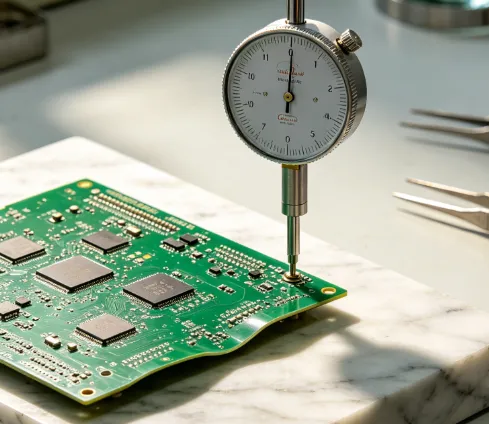
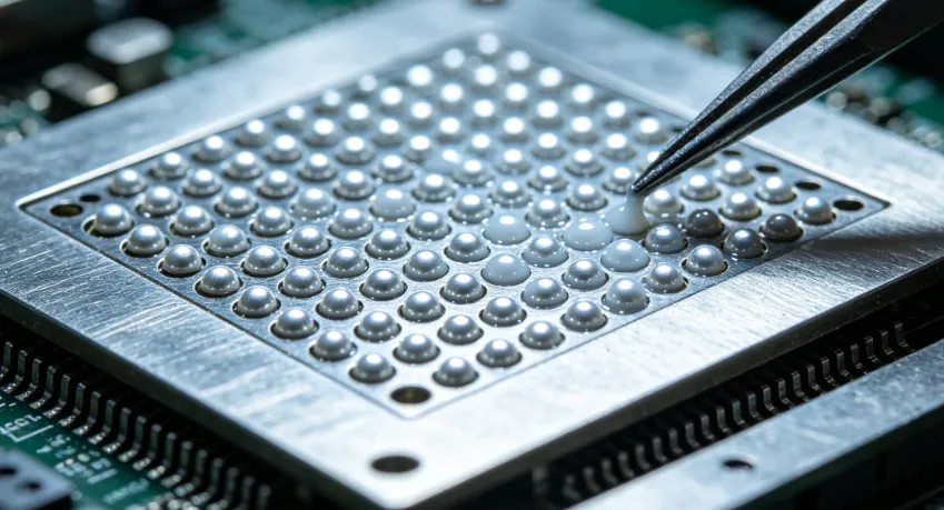
Preparation begins with thorough inspection of the target area using optical or X-ray equipment to confirm the defect location and assess pad condition. The board is then secured in a fixture that supports even heating and prevents movement during the operation. A BGA rework station applies a programmed thermal profile that ramps the component and board to reflow temperature, allowing the solder to liquefy for safe removal. Once extracted, the site is cleaned of residual solder using a vacuum or solder wick while the board remains at a controlled temperature. Reballing follows, in which new solder spheres are placed and reflowed onto the component pads under a nitrogen atmosphere to minimize oxidation. Final placement and soldering complete the sequence, with post-process inspection verifying alignment and joint quality.
Related Reading: BGA Rework for Beginners: A Hobbyist's Guide to Repairing Electronics
Best Practices and Tools for BGA Rework
Engineers rely on a combination of BGA rework tools that include precision hot-air nozzles, bottom-side heaters, and automated vision alignment systems. Consistent use of these tools reduces the risk of pad lifting or component cracking during repeated thermal excursions. Process parameters should be validated on test boards before production units are processed, ensuring the chosen profile stays within material limits. Documentation of each rework event, including temperature data and inspection results, supports traceability and continuous improvement. When performed correctly, these practices align with requirements outlined in IPC-A-610 for electronic assembly acceptance.
Related Reading: BGA Rework Demystified: A Practical Guide to Hot Air Techniques
Troubleshooting Common Issues in BGA Rework
Incomplete solder reflow often stems from insufficient dwell time at peak temperature or inadequate flux activation. In such cases, adjusting the profile to extend the time above liquidus while monitoring board warpage prevents recurrence. Bridging between adjacent balls can result from excess solder volume or misalignment during placement; corrective action involves reducing paste deposit and verifying vision system calibration. Moisture-related damage appears as popcorn cracking or delamination and is avoided by following proper baking procedures prior to rework. Systematic root-cause analysis of each failure mode improves first-pass success rates over time.
Conclusion
Mastering advanced BGA rework techniques enables engineers to recover valuable assemblies while maintaining high reliability standards. A structured approach that combines accurate thermal profiling, proper tooling, and adherence to industry guidelines consistently delivers acceptable results. Continued refinement of these methods supports the evolving demands of high-density electronics manufacturing.
FAQs
Q1: What equipment is essential for a successful BGA rework process?
A1: A dedicated BGA rework station equipped with top and bottom heating, precise nozzle control, and vision alignment forms the core of any effective setup. Supporting tools such as solder removal devices, reballing stencils, and inspection systems complete the workstation. Engineers select equipment based on board size, component pitch, and production volume to ensure repeatable outcomes.
Q2: How does BGA reballing differ from standard soldering BGA components?
A2: BGA reballing restores the solder sphere array on a removed or new package before it is placed onto the board. In contrast, soldering BGA components typically involves applying solder paste to the board pads and then positioning the component for reflow. Both operations require controlled heating, yet reballing adds an extra step of sphere placement and reflow on the package itself.
Q3: Which BGA rework tools help prevent board damage during removal?
A3: Bottom-side preheaters and adjustable hot-air nozzles distribute heat evenly, reducing localized stress on the substrate. Fixturing systems that support the board at multiple points further limit flexure and warpage. Proper selection and calibration of these BGA rework tools directly influence the success rate of the overall process.
Q4: Why is process profiling critical when using a BGA rework station?
A4: Accurate thermal profiling ensures the solder reaches reflow temperature uniformly while the board and component remain within safe limits. Deviations can cause incomplete joints, excessive warpage, or damage to nearby parts. Documented profiles validated against board-specific thermal characteristics provide the foundation for consistent, high-yield results.
References
IPC-A-610G - Acceptability of Electronic Assemblies. IPC, 2017
JEDEC J-STD-020E - Moisture/Reflow Sensitivity Classification for Nonhermetic Surface Mount Devices. JEDEC, 2014
IPC-7711/7721B - Rework, Modification and Repair of Electronic Assemblies. IPC, 2017


