 ALLPCB


Are you struggling to find the ideal flex PCB thickness for your project? Determining the optimal thickness for a flexible circuit board can feel like a balancing act—too thick, and you lose flexibility; too thin, and durability suffers. The sweet spot, or "Goldilocks Zone," for flex PCB thickness typically ranges between 0.1 mm to 0.5 mm for most applications, depending on factors like flexibility needs, layer count, and environmental conditions. In this comprehensive guide, we'll dive deep into how to determine flex PCB thickness, explore the factors influencing it, and provide actionable insights to help you design a reliable and efficient flexible circuit for your next innovation.
Why Flex PCB Thickness Matters in Your Design
Flexible printed circuit boards (flex PCBs) are a game-changer in modern electronics, enabling compact, lightweight, and adaptable designs in everything from wearables to medical devices. Unlike rigid PCBs, flex circuits can bend, fold, and twist, making them ideal for tight spaces and dynamic applications. However, the thickness of a flex PCB directly impacts its performance, cost, and manufacturability. Choosing the right thickness ensures your circuit can handle mechanical stress, maintain signal integrity, and fit within your product's spatial constraints.
Getting the thickness wrong can lead to issues like cracking under repeated bending (if too thick) or insufficient structural support for components (if too thin). So, finding that perfect balance is critical for both functionality and longevity.
Understanding the Basics of Flex PCB Thickness
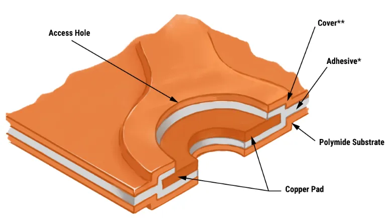
Flex PCB thickness is determined by the combined thickness of its layers, which typically include a flexible substrate (like polyimide), copper traces, adhesive layers, and protective coverlays. The total thickness can range from as thin as 0.05 mm for ultra-flexible single-layer designs to over 1 mm for complex multilayer flex circuits.
Here are the primary components that contribute to thickness:
- Substrate Material: Often made of polyimide, with thicknesses ranging from 12.5 microns (0.0125 mm) to 125 microns (0.125 mm). Thinner substrates offer greater flexibility but less durability.
- Copper Layers: Copper thickness is measured in ounces per square foot (oz/ft2), where 1 oz equals about 35 microns (0.035 mm). Common options are 0.5 oz to 2 oz, depending on current-carrying needs.
- Adhesive and Coverlay: These protective and bonding layers add another 25 to 50 microns (0.025 to 0.05 mm) per layer, depending on the design.
For a single-layer flex PCB, you might start with a total thickness of around 0.1 to 0.2 mm, while a multilayer design could easily reach 0.5 mm or more. Understanding these building blocks is the first step in determining the optimal thickness for your flexible circuit board.
Factors to Consider When Determining Flex PCB Thickness
Choosing the ideal flex PCB thickness isn't a one-size-fits-all decision. Several factors come into play, each influencing how thick or thin your board should be. Let’s break them down:
1. Flexibility and Bend Radius Requirements
The primary advantage of flex PCBs is their ability to bend. If your application requires tight bends or repeated flexing (like in a folding smartphone or wearable device), a thinner board—typically 0.1 to 0.2 mm—is essential. Thinner boards can achieve a smaller bend radius, often as tight as 3 to 5 times the board’s thickness. For example, a 0.1 mm thick flex PCB can handle a bend radius of 0.3 to 0.5 mm without risking damage.
On the other hand, if flexibility is less critical and the board will remain mostly static, a thicker design (0.3 to 0.5 mm) can provide better structural support and ease of handling during assembly.
2. Layer Count and Circuit Complexity
The number of layers in your flexible PCBs directly affects their thickness. A single-layer flex might be as thin as 0.1 mm, while a 4 layer PCB design could reach 0.4 to 0.6 mm due to additional copper and dielectric layers. More layers mean higher density for complex circuits, but they also reduce flexibility. If your project involves high-speed signals or intricate routing, you might need multiple layers, pushing the thickness beyond the ultra-thin range.
3. Current and Power Requirements
The thickness of copper layers impacts how much current your flex PCB can carry. For high-power applications, thicker copper (e.g., 2 oz or 70 microns) is necessary to prevent overheating and voltage drops. This increases the overall board thickness. For low-power designs, such as sensors in IoT devices, thinner copper (0.5 oz or 17.5 microns) suffices, allowing for a slimmer profile.
For instance, a flex PCB carrying 5 amps might require 2 oz copper, adding at least 0.07 mm to the stack-up, whereas a signal-only circuit could use 0.5 oz copper, contributing just 0.0175 mm.
4. Environmental and Mechanical Stress
Consider where and how your flex PCB will be used. If it’s exposed to vibration, thermal cycling, or harsh conditions (like in automotive or aerospace applications), a slightly thicker board (0.3 to 0.5 mm) with robust materials can improve durability. Thinner boards are more prone to tearing or cracking under mechanical stress, especially during repeated flexing cycles.

5. Signal Integrity for High-Speed Applications
In high-frequency designs, such as those for 5G devices or high-speed data transmission, signal integrity is critical. The dielectric thickness between copper layers affects impedance, which must be controlled (often at 50 ohms for RF signals). A thinner dielectric reduces crosstalk but may require precise manufacturing. For example, a flex PCB with a 50-micron dielectric layer might be necessary to maintain signal speeds above 1 GHz, influencing the total thickness to stay around 0.2 to 0.3 mm.
6. Cost and Manufacturability
Thinner flex PCBs are often more expensive to produce due to the precision required in handling and fabrication. Conversely, extremely thick flex boards may increase material costs. Most manufacturers can comfortably produce flex PCBs in the 0.1 to 0.5 mm range without significant cost spikes. Balancing performance with budget is key when determining thickness.
How to Determine the Optimal Flex PCB Thickness for Your Project
Now that you understand the factors at play, let’s walk through a practical approach to finding the ideal flex PCB thickness for your design:
- Define Your Application Needs: Start by identifying the primary function of your flex PCB. Does it need to bend repeatedly, or will it remain static? Will it carry high current or operate at high frequencies? For dynamic applications, aim for 0.1 to 0.2 mm; for static or high-power uses, consider 0.3 to 0.5 mm.
- Calculate Layer Stack-Up: Work with your design software to build a tentative stack-up. Include substrate, copper, adhesive, and coverlay thicknesses. A typical single-layer stack-up might be: 25 microns substrate + 17.5 microns copper + 25 microns coverlay = 0.0675 mm total. Adjust based on layer count.
- Test Bend Radius: If flexibility is critical, simulate or prototype the bend radius. Ensure the thickness allows bending without stress. A general rule is that the bend radius should be at least 3 to 5 times the board thickness for dynamic flexing.
- Verify Signal and Power Needs: Use impedance calculators or consult with your manufacturer to ensure dielectric thickness supports signal integrity (e.g., maintaining 50 ohms for RF). For power, confirm copper thickness supports current without excessive heat (e.g., 1 oz copper for up to 2-3 amps).
- Consider Manufacturing Limits: Check with your fabrication partner for minimum and maximum thickness capabilities. Most can handle 0.1 to 0.5 mm without issues, but ultra-thin or thick designs may require specialized processes.
Common Flex PCB Thickness Ranges for Different Applications
To give you a clearer idea of what thickness might suit your project, here are some standard ranges based on application:
- Wearables (e.g., fitness trackers): 0.1 to 0.15 mm for maximum flexibility and lightweight design.
- Medical Devices (e.g., implantable sensors): 0.1 to 0.2 mm to fit in confined spaces while ensuring biocompatibility.
- Automotive Electronics (e.g., dashboard controls): 0.3 to 0.5 mm for durability under vibration and temperature swings.
- Consumer Electronics (e.g., smartphones): 0.2 to 0.4 mm to balance flexibility with multilayer complexity.
- Aerospace (e.g., satellite systems): 0.3 to 0.6 mm for robustness and high-reliability signal transmission.
Tips for Balancing Flexibility and Durability
Achieving the optimal thickness for a flexible circuit board often means balancing opposing needs. Here are some tips to help:
- Use thinner copper (0.5 oz) in areas that don’t carry high current to reduce overall thickness without sacrificing flexibility.
- Add stiffeners (like polyimide or FR-4) only in specific areas where components are mounted, keeping the rest of the board thin for bending.
- Opt for high-quality substrate materials like polyimide with a lower thickness (e.g., 12.5 microns) to maintain flexibility while ensuring tear resistance.
- Simulate mechanical stress during the design phase to predict failure points and adjust thickness accordingly.
Partnering with Experts for Precision Flex PCB Design
Determining the ideal flex PCB thickness can be complex, especially for cutting-edge applications with strict performance requirements. Working with an experienced manufacturing partner can make all the difference. At ALLPCB, we offer tailored solutions to help you navigate stack-up design, material selection, and thickness optimization. Our team ensures your flex circuit meets both technical and budget goals, delivering high-quality boards for any application.

Conclusion: Hitting the Sweet Spot for Flex PCB Thickness
Finding the perfect PCB thickness for your flex circuit—the Goldilocks Zone—requires careful consideration of flexibility, durability, signal needs, and cost. Most designs will fall within the 0.1 to 0.5 mm range, but the exact value depends on your unique application. By understanding the factors that influence thickness and following a structured approach to determine the optimal value, you can create a flex PCB that performs reliably and fits seamlessly into your product.
Whether you're designing for wearables, automotive systems, or high-speed electronics, the right thickness ensures your flex circuit is neither too thick nor too thin—just right. With the insights from this guide, you're well-equipped to make informed decisions and bring your innovative designs to life.


