ALLPCB


Designing a 10-layer PCB can be a complex task, especially when balancing signal integrity and high-density routing. Whether you're working on high-speed digital circuits or compact designs, mastering 10-layer PCB routing techniques is essential for optimal performance. In this comprehensive guide, we’ll dive into proven strategies for 10-layer PCB high-density routing and 10-layer PCB differential pair routing, ensuring your designs are both efficient and reliable.
At its core, a 10-layer PCB offers multiple layers for routing signals, power, and ground planes, which helps in managing complex circuits with minimal interference. However, improper routing can lead to signal degradation, crosstalk, and electromagnetic interference (EMI). This blog will walk you through actionable tips and best practices to tackle these challenges, from stackup design to differential pair routing, all tailored for a 10-layer board.
Why 10-Layer PCBs Matter in Modern Electronics
In today’s electronics, devices are becoming smaller, faster, and more powerful. A 10-layer PCB provides the necessary space to route intricate circuits while maintaining signal integrity. These boards are commonly used in applications like telecommunications, medical devices, and high-speed computing systems where multiple high-speed signals and dense component placement are required.
With 10 layers, you have the flexibility to dedicate specific layers to power and ground planes, which helps in reducing noise and improving signal quality. However, the increased number of layers also means more complexity in routing and a higher risk of issues like signal reflection or impedance mismatch if not handled correctly.

Key Challenges in 10-Layer PCB Routing
Before diving into specific 10-layer PCB routing techniques, it’s important to understand the main challenges you’ll face:
- Signal Integrity: High-speed signals can suffer from reflections, crosstalk, and timing issues if traces are not routed properly.
- High-Density Routing: With more components packed into smaller spaces, routing in a 10-layer PCB requires careful planning to avoid congestion.
- EMI and Noise: Without proper grounding and shielding, electromagnetic interference can degrade performance.
- Impedance Control: Maintaining consistent impedance for high-speed signals, especially differential pairs, is critical.
Addressing these challenges starts with a well-thought-out design approach. Let’s explore the strategies that can help you succeed.
Strategy 1: Optimize Your 10-Layer PCB Stackup Design
The foundation of effective 10-layer PCB high-density routing lies in a well-planned stackup. A typical 10-layer stackup might look like this:
- Layer 1: Top Signal Layer
- Layer 2: Ground Plane
- Layer 3: Signal Layer
- Layer 4: Power Plane
- Layer 5: Signal Layer
- Layer 6: Ground Plane
- Layer 7: Signal Layer
- Layer 8: Power Plane
- Layer 9: Ground Plane
- Layer 10: Bottom Signal Layer
This configuration alternates signal layers with ground and power planes to minimize noise and provide a return path for signals. Ground planes adjacent to signal layers help in reducing crosstalk by acting as a shield. For high-speed designs, ensure that critical signals are routed on layers close to a ground plane to maintain signal integrity.
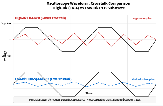
When designing your stackup, consider the dielectric material’s thickness and properties. For instance, a dielectric constant (Dk) of around 3.5 to 4.5 is common for FR-4 materials used in high-speed designs. Thinner dielectrics between layers can help reduce loop inductance but may increase manufacturing costs.

Strategy 2: Prioritize 10-Layer PCB High-Density Routing
High-density routing is a critical aspect of 10-layer PCB design, especially when dealing with compact layouts. Here are some practical tips for 10-layer PCB high-density routing:
- Use Microvias and Blind Vias: These smaller vias save space compared to through-hole vias and allow for tighter routing in dense areas. Microvias can connect adjacent layers without occupying space on all layers.
- Route Critical Nets First: Start with high-speed signals and differential pairs before routing less critical traces. This ensures they get the shortest and cleanest paths.
- Leverage Multiple Layers: Distribute traces across different layers to avoid congestion. For instance, route horizontal traces on one layer and vertical traces on another to minimize overlap.
- Minimize Trace Lengths: Shorter traces reduce signal delay and lower the risk of interference. Aim for direct paths whenever possible.
In a 10-layer PCB, you can dedicate internal layers to high-density routing while keeping outer layers for component placement and shorter connections. This approach helps manage space efficiently while reducing the risk of signal issues.

Strategy 3: Master 10-Layer PCB Differential Pair Routing
Differential pair routing is crucial for high-speed signals like USB, Ethernet, or PCIe, which are common in modern electronics. Proper 10-layer PCB differential pair routing ensures minimal noise and consistent signal timing. Follow these guidelines:
- Maintain Equal Lengths: Both traces in a differential pair must be of equal length to avoid timing skew. A mismatch as small as 5 mils can cause signal delays in high-speed designs operating at 10 Gbps or higher.
- Control Impedance: Differential pairs typically require a specific impedance, such as 100 ohms for USB 3.0. Use trace width and spacing calculators to match the impedance based on your stackup and dielectric material.
- Keep Pairs Close: Route the two traces of a differential pair close together to ensure they experience the same noise environment, which cancels out common-mode noise.
- Avoid Sharp Bends: Use smooth curves or 45-degree angles instead of 90-degree bends to prevent signal reflections.
- Route Near Ground Planes: Place differential pairs on layers adjacent to a ground plane to provide a stable return path and reduce EMI.
In a 10-layer PCB, you can dedicate specific internal layers for differential pairs, sandwiching them between ground planes for optimal shielding. This setup is particularly effective for maintaining signal integrity in high-speed applications.

Strategy 4: Ensure Signal Integrity Across All Layers
Signal integrity is the cornerstone of a successful 10-layer PCB design. Poor signal integrity can lead to data errors, timing issues, and system failures. Here’s how to maintain it:
- Minimize Crosstalk: Space traces apart based on their signal speed. For high-speed signals, maintain a spacing of at least 3 times the trace width to reduce crosstalk.
- Use Proper Termination: Terminate high-speed signals with resistors or other components to match impedance and prevent reflections. For example, a 50-ohm termination is common for many RF signals.
- Manage Return Paths: Ensure every signal has a continuous return path on an adjacent ground plane. Avoid splitting ground planes under high-speed traces as it disrupts the return path.
- Control Signal Transitions: When a signal transitions between layers using vias, place a ground via nearby to provide a return path and minimize impedance discontinuity.
By carefully planning your routing and stackup, a 10-layer PCB can handle high-speed signals with minimal degradation. Regularly simulate your design using tools to check for signal integrity issues before manufacturing.
Strategy 5: Manage Power Distribution and Grounding
A robust power distribution network (PDN) and grounding strategy are vital for a 10-layer PCB. Poor power delivery can cause voltage drops, while inadequate grounding increases noise. Follow these tips:
- Dedicate Layers to Power and Ground: Use multiple layers for power and ground planes to reduce resistance and ensure stable voltage delivery. In a 10-layer PCB, having at least two ground planes and one or two power planes is ideal.
- Place Decoupling Capacitors: Position decoupling capacitors close to power pins of ICs to filter noise. Use a mix of capacitor values (e.g., 0.1 μF and 1 μF) to cover a wide frequency range.
- Avoid Ground Loops: Ensure ground planes are continuous and connected through vias at multiple points to prevent loops that can pick up noise.
A well-designed PDN in a 10-layer PCB ensures that all components receive clean power, which directly impacts signal integrity and overall performance.
Strategy 6: Test and Iterate Your Design
Even with the best planning, issues can arise in a 10-layer PCB design. Testing and iteration are key to achieving perfection. Use these steps:
- Simulate Early: Run simulations for signal integrity, power integrity, and EMI during the design phase to catch potential problems.
- Prototype and Test: Build a prototype and test it under real-world conditions. Use oscilloscopes to measure signal quality and identify issues like overshoot or ringing.
- Refine Based on Results: Adjust trace widths, spacing, or stackup based on test data to improve performance.
Iterating on your design ensures that your 10-layer PCB meets the required specifications for signal integrity and density.
Conclusion: Building Better 10-Layer PCBs
Mastering 10-layer PCB routing techniques is a game-changer for engineers working on complex, high-speed, or high-density designs. By focusing on stackup optimization, high-density routing strategies, differential pair routing, and signal integrity, you can create boards that perform reliably under demanding conditions. A 10-layer PCB offers ample space to manage intricate circuits, but only if you apply these strategies with precision.
Start with a solid stackup design, prioritize critical nets, and use the multiple layers to your advantage for both 10-layer PCB high-density routing and 10-layer PCB differential pair routing. Regularly simulate and test your designs to catch issues early and refine your approach. With these practices, you’ll be well-equipped to handle the challenges of modern PCB design and deliver exceptional results.