ALLPCB


If you're looking to master SMT assembly, using stencils effectively for solder paste application is key. This process ensures precise placement of solder paste on PCB pads, creating reliable connections for surface mount components. In this comprehensive guide, we'll dive deep into SMT stencil design, solder paste application, stencil thickness, stencil materials, and the overall SMT process to help you achieve optimal results in your assembly projects.
What Are SMT Stencils and Why Are They Important?
SMT stencils are thin sheets, typically made of stainless steel, with laser-cut openings that match the layout of the pads on a printed circuit board (PCB). Their primary role in the SMT process is to control the amount and placement of solder paste during assembly. By using a squeegee to push solder paste through these openings, you ensure that the right amount of paste lands exactly where it's needed for component placement.
The importance of stencils cannot be overstated. Poor stencil design or application can lead to issues like insufficient solder, bridging, or misalignment, which result in defective boards. Getting it right saves time, reduces waste, and ensures high-quality electrical connections between components and the PCB.
Key Elements of SMT Stencil Design
Creating an effective SMT stencil design is the foundation of successful solder paste application. A well-designed stencil ensures consistent paste deposition, which directly impacts the quality of solder joints. Let's break down the critical factors to consider:
1. Aperture Size and Shape
The apertures (openings) in the stencil must match the size and shape of the PCB pads, but they aren't always a 1:1 ratio. For most components, a slightly smaller aperture—about 10-20% reduction in area—helps prevent excess paste and reduces the risk of bridging. For fine-pitch components, such as those with a pitch of 0.5mm or less, even tighter tolerances may be necessary.
2. Stencil Alignment and Fiducials
Alignment is crucial in the SMT process. Fiducial marks—small reference points on the stencil and PCB—help automated machines position the stencil accurately. These marks are typically 1mm in diameter and can be half-laser-etched (a shallow mark) or fully laser-cut through the stencil for maximum precision.
3. Frame vs. Frameless Stencils
Stencils come in two main types: framed and frameless. Framed stencils are mounted in a rigid frame, ideal for high-volume production with automated equipment, as they provide stability during repeated use. Frameless stencils, on the other hand, are lighter and more cost-effective for manual or low-volume assembly. Choosing the right type depends on your production needs and budget.

Choosing the Right Stencil Thickness
Stencil thickness plays a major role in determining how much solder paste is deposited on the PCB. If the stencil is too thick, you risk applying too much paste, leading to bridging or short circuits. If it's too thin, insufficient paste can cause weak solder joints. Here's how to choose the right thickness:
- Standard Thickness: For most SMT applications, a thickness of 0.1mm to 0.15mm (4 to 6 mils) works well. This range suits components with pitches between 0.65mm and 1.27mm.
- Fine-Pitch Components: For components with pitches below 0.5mm, such as QFN or BGA packages, a thinner stencil of 0.08mm to 0.1mm (3 to 4 mils) is often better to control paste volume.
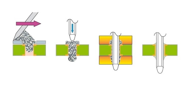
- Large Components: For larger components or through-hole parts, a thicker stencil of 0.2mm (8 mils) may be necessary to deposit enough paste for a strong joint.
The general rule is to balance the stencil thickness with the component size and pitch. Testing different thicknesses during prototyping can help you dial in the perfect setting for your specific board design.
Understanding Stencil Materials
The choice of stencil materials affects durability, precision, and cost. Most stencils are made from stainless steel due to its excellent properties, but there are other options and considerations:
1. Stainless Steel
Stainless steel is the most common material for SMT stencils. It offers high durability, resistance to wear, and compatibility with laser-cutting for precise apertures. It can withstand thousands of print cycles, making it ideal for both prototype and production runs.
2. Nickel-Plated Stencils
Some manufacturers offer nickel-plated stainless steel stencils for improved solder paste release. The smooth surface of nickel reduces paste sticking to the stencil walls, which is especially helpful for fine-pitch applications. However, these stencils are more expensive and may not be necessary for standard projects.
3. Polyimide or Plastic Stencils
For very low-volume or one-off prototypes, polyimide or plastic stencils can be a cheaper alternative. They are less durable and prone to wear after just a few uses, so they’re not recommended for production environments.
When selecting a material, prioritize durability and precision over cost if you're working on high-reliability projects. A high-quality stencil pays for itself by reducing defects and rework.

Best Practices for Solder Paste Application
Effective solder paste application is where stencil design and process execution come together. Follow these best practices to ensure consistent results in your SMT assembly:
1. Prepare the Stencil and PCB
Before starting, clean both the stencil and PCB to remove any dust, debris, or residue. Even small particles can interfere with paste deposition or cause misalignment. Use isopropyl alcohol and a lint-free cloth for cleaning, and ensure the stencil is securely aligned with the PCB using fiducial marks or manual alignment if necessary.
2. Use the Right Squeegee
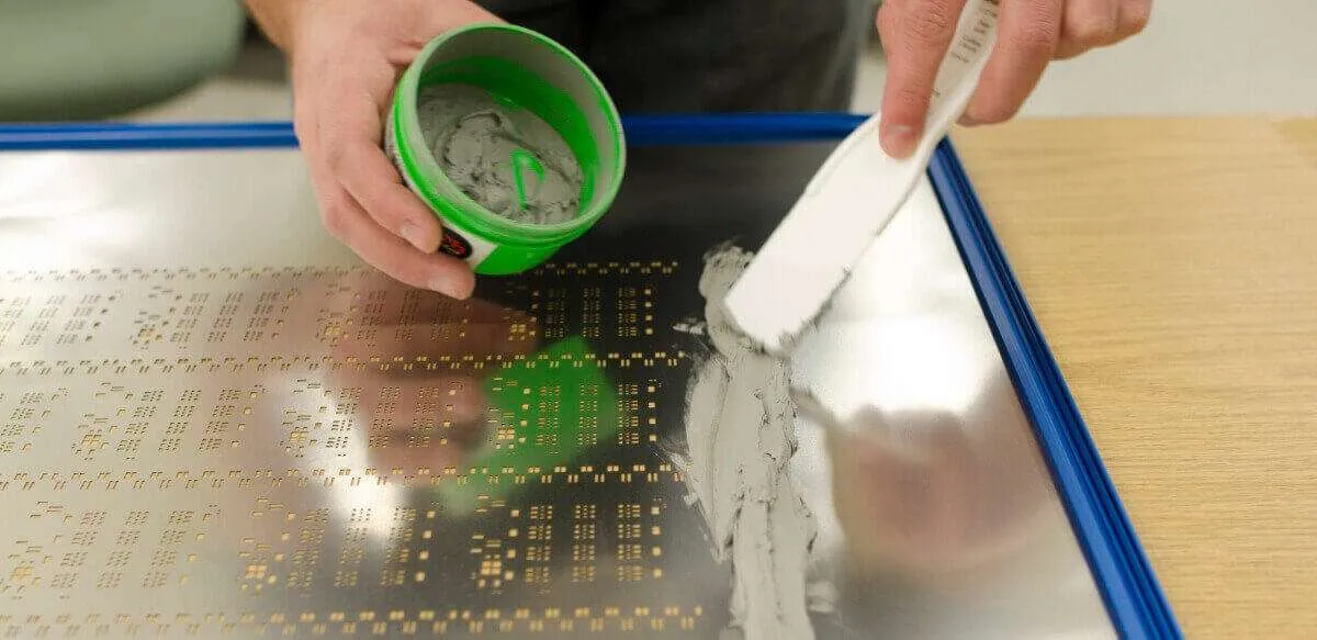
The squeegee is the tool used to push solder paste through the stencil apertures. A metal squeegee with a 60-degree angle is standard for most applications, as it provides good control over paste distribution. Apply consistent pressure and maintain a steady speed—too fast, and you might miss spots; too slow, and you risk over-depositing paste.
3. Control Solder Paste Volume
Only apply enough solder paste to cover about two-thirds of the squeegee length. Adding too much paste can lead to mess and waste, while too little can result in incomplete coverage. A typical starting amount for a 200mm squeegee is about 20-30 grams of paste, adjusted based on stencil size and design.
4. Inspect After Printing
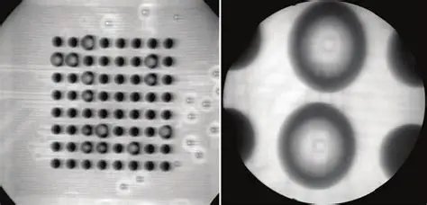
After applying the paste, lift the stencil carefully to avoid smudging. Inspect the PCB under magnification to check for uniform paste deposits. Look for issues like incomplete coverage, excess paste, or bridging between pads. If you spot problems, clean the stencil and PCB, then reprint.
Common Challenges in the SMT Process and How to Overcome Them
Even with the best SMT stencil design and techniques, challenges can arise during the SMT process. Here are some common issues and solutions:
1. Solder Paste Bridging
Bridging happens when excess paste connects adjacent pads, often due to overly large apertures or excessive stencil thickness. To fix this, reduce aperture size by 10-15% or switch to a thinner stencil. Also, ensure the squeegee pressure isn't too high, as this can force extra paste through the openings.
2. Insufficient Solder Paste
If pads have too little paste, components may not form proper joints during reflow. This can result from a stencil that's too thin or apertures that are too small. Increase the stencil thickness by 0.02mm or adjust the aperture design to allow more paste through.
3. Stencil Wear and Damage
Over time, stencils can wear out, especially if not cleaned properly after each use. Solder paste residue can build up in apertures, leading to inconsistent deposits. Clean the stencil with a dedicated solvent or ultrasonic cleaner after every 5-10 prints, and store it flat to prevent bending.
Advanced Tips for Optimizing SMT Stencil Use
For those looking to take their SMT process to the next level, consider these advanced strategies:
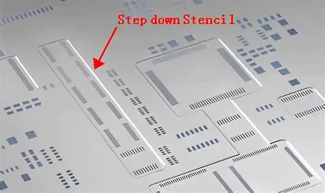
- Step Stencils: For boards with mixed component sizes, a step stencil with varying thicknesses in different areas can optimize paste volume. For example, use a 0.1mm thickness for fine-pitch areas and 0.15mm for larger components on the same board.
- Nano-Coatings: Some stencils come with nano-coatings to improve paste release and reduce cleaning frequency. These are particularly useful for high-density boards with pitches below 0.4mm.
- Automated Inspection: Use automated optical inspection (AOI) systems after paste application to catch defects early. These systems can detect issues with paste volume and alignment at a resolution of 10 microns or better.

Conclusion: Mastering Stencils for SMT Success
Using stencils effectively in SMT assembly is all about precision and attention to detail. From designing the right SMT stencil with proper aperture sizes to selecting the ideal stencil thickness and materials, every step matters. By following best practices for solder paste application and troubleshooting common issues, you can achieve consistent, high-quality results in your SMT process.
Whether you're a hobbyist assembling a small batch of boards or a professional managing high-volume production, the insights in this guide can help you refine your approach. Invest time in testing and optimizing your stencil setup, and you'll see fewer defects, better solder joints, and more reliable PCBs. With the right tools and techniques, mastering SMT assembly is within your reach.