 ALLPCB


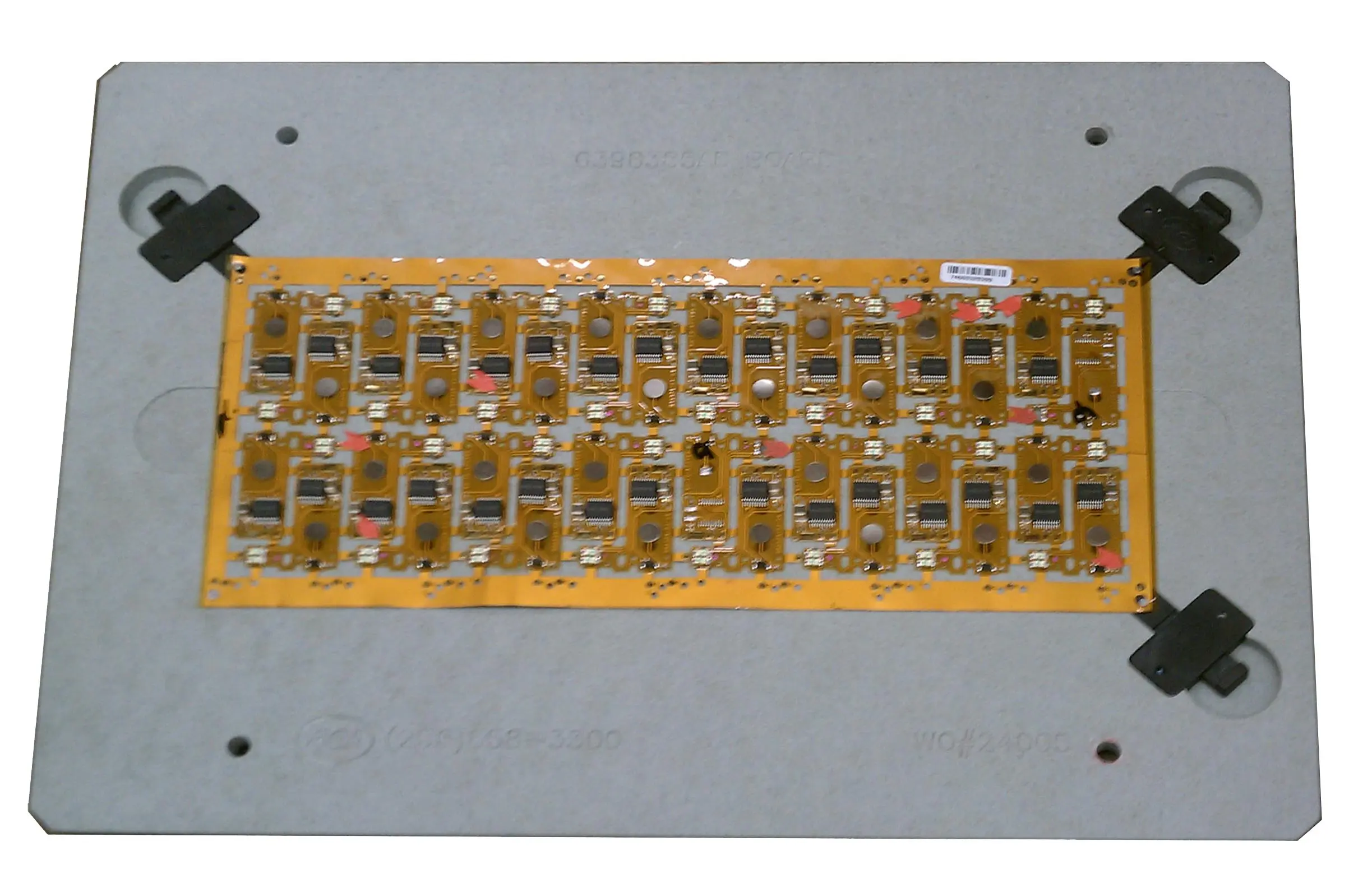
Flexible printed circuit boards (flex PCBs) are vital in modern electronics, offering unique advantages in space-constrained and portable devices. However, assembling flex PCBs can be challenging due to their delicate nature, often leading to defects like soldering issues, component misalignment, and unreliable solder joints. If you're facing problems with flex PCB soldering defects, component misalignment on flex boards, solder joint reliability on flex PCBs, rework procedures for flexible PCBs, or conformal coating issues on flex PCBs, this practical handbook from ALLPCB is here to help. We'll guide you through identifying, troubleshooting, and resolving these common assembly defects with actionable solutions.
In this comprehensive guide, we dive deep into the most frequent issues encountered during flex PCB assembly. From understanding the root causes to implementing effective fixes, this blog will equip you with the knowledge to improve assembly quality and ensure reliable performance for your electronic designs.
Why Flex PCB Assembly Defects Matter
Flex PCBs are designed to bend and fit into tight spaces, making them ideal for applications like wearables, medical devices, and automotive electronics. However, their flexibility also makes them prone to assembly defects that can compromise functionality. Issues such as poor soldering or misaligned components can lead to electrical failures, reduced product lifespan, or costly rework. By addressing these defects early, you can save time, reduce production costs, and ensure your devices meet performance standards.
Let’s explore the most common flex PCB assembly defects and provide practical solutions for each, helping you achieve high-quality results in your projects.
1. Flex PCB Soldering Defects: Causes and Solutions
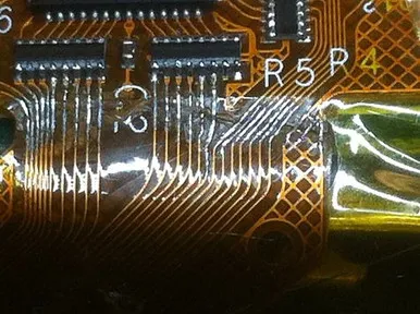
Soldering is a critical step in flex PCB assembly, but the thin and delicate materials used in these boards can make it tricky. Common flex PCB soldering defects include cold solder joints, solder bridges, and lifted pads. These issues can disrupt electrical connections and lead to device failure.
Common Soldering Defects
- Cold Solder Joints: These occur when the solder doesn’t fully melt or bond with the pad and component lead, often due to insufficient heat. This results in weak, unreliable connections that can crack under stress.
- Solder Bridges: Excess solder can create unintended connections between adjacent pads or traces, causing short circuits.
- Lifted Pads: Excessive heat or mechanical stress during soldering can lift the copper pads off the flexible substrate, breaking the connection.
Solutions for Soldering Defects
- Control Heat Precisely: Use a soldering iron with adjustable temperature settings, ideally between 260°C and 300°C for most flex PCB materials. Avoid overheating, as it can damage the substrate or lift pads. A controlled heat source ensures proper solder flow without risking thermal damage.
- Use Adequate Flux: Apply flux to clean the surfaces and improve solder wetting. This reduces the risk of cold joints by ensuring a strong bond between the solder and the pad.
- Support the Board: Flex PCBs can bend during soldering, leading to uneven heat distribution. Use a flat, heat-resistant surface or fixture to hold the board steady while working.
- Inspect Joints Visually: After soldering, inspect each joint with a magnifying glass or microscope to check for cracks, bridges, or incomplete bonds. Early detection prevents issues down the line.

2. Component Misalignment on Flex Boards: Identifying and Fixing
Component misalignment on flex boards is another frequent issue during assembly. Due to the flexible nature of the substrate, components can shift during placement or soldering, leading to poor connections or mechanical stress.
Causes of Misalignment
- Board Flexibility: Flex PCBs can warp or bend during handling, causing components to move out of position.
- Inaccurate Placement: Manual or automated placement errors, especially with small surface-mount components, can result in misalignment.
- Solder Reflow Issues: During reflow soldering, uneven heating can cause components to shift if not secured properly.
Solutions to Prevent Misalignment
- Use Fixtures or Jigs: Secure the flex PCB in a rigid fixture during component placement and soldering to prevent bending or shifting. This ensures components stay in their designated positions.
- Optimize Stencil Design: For surface-mount components, ensure the solder paste stencil is precisely aligned with the pads. A stencil with accurate apertures helps deposit the right amount of paste, holding components in place during reflow.
- Adjust Reflow Profiles: Fine-tune the reflow oven temperature profile to avoid rapid heating or cooling, which can cause components to move. A gradual ramp-up to a peak temperature of around 245°C for lead-free solder, followed by controlled cooling, minimizes thermal shock.
- Visual Inspection: Use automated optical inspection (AOI) or manual checks after placement to confirm component alignment before soldering. Correct any misaligned parts before proceeding.
3. Solder Joint Reliability on Flex PCBs: Ensuring Long-Term Performance
Solder joint reliability on flex PCBs is critical for maintaining electrical and mechanical integrity, especially since these boards are subject to repeated bending and vibration in applications like wearables or automotive systems. Poor solder joints can crack or fail over time, leading to intermittent connections or complete failure.
Factors Affecting Solder Joint Reliability
- Mechanical Stress: Flex PCBs endure bending and flexing, which can stress solder joints and cause fatigue cracks.
- Thermal Cycling: Temperature fluctuations during operation can expand and contract solder joints, leading to cracks if the joint isn’t robust.
- Material Mismatch: Differences in the coefficient of thermal expansion (CTE) between the flex substrate, components, and solder can create stress points.
Strategies to Improve Reliability
- Use Flexible Solder Alloys: Opt for solder alloys with higher flexibility, such as tin-silver-copper (SAC) compositions like SAC305, which offer better resistance to mechanical stress compared to traditional tin-lead solders.
- Reinforce Joints: Apply underfill or epoxy reinforcement around critical solder joints to provide mechanical support and reduce stress during flexing.
- Design for Flexibility: During the PCB design phase, avoid placing large or heavy components in areas prone to bending. Distribute stress evenly by routing traces and placing components strategically.
- Test for Reliability: Conduct thermal cycling tests (e.g., -40°C to 85°C for 1000 cycles) and mechanical bend tests to simulate real-world conditions and ensure solder joints hold up over time.
4. Rework Procedures for Flexible PCBs: Best Practices
When defects occur, rework becomes necessary. However, rework procedures for flexible PCBs require extra care due to the delicate substrate and risk of further damage. Improper rework can worsen issues like lifted pads or torn traces.
Common Rework Challenges
- Heat Sensitivity: Excessive heat during desoldering can damage the flexible substrate or nearby components.
- Fragile Traces: Flex PCBs often have thinner copper traces that can tear during component removal or replacement.
- Limited Access: Tight spaces in flex PCB designs can make rework tools difficult to maneuver.
Effective Rework Techniques
- Use Low-Temperature Tools: Employ a hot air rework station with precise temperature control (set to around 250°C for desoldering) to minimize thermal damage. Shield nearby components with heat-resistant tape if needed.
- Protect the Board: Place a heat-resistant mat or fixture under the flex PCB to prevent bending or tearing during rework. Avoid excessive force when removing components.
- Repair Damaged Traces: If a trace is damaged during rework, use conductive epoxy or jumper wires to restore connectivity. Ensure the repair is secure and insulated to prevent shorts.
- Document the Process: Keep a detailed log of rework steps, including tools used and issues encountered, to refine future procedures and prevent recurring defects.
5. Conformal Coating Issues on Flex PCBs: Prevention and Fixes
Conformal coating issues on flex PCBs can compromise the board’s protection against moisture, dust, and mechanical stress. Common problems include uneven coating, peeling, or cracking, especially in areas subject to bending.
Causes of Coating Issues
- Improper Application: Uneven spraying or brushing can leave thin spots or bubbles in the coating, reducing protection.
- Incompatible Materials: Some coatings may not adhere well to the flex PCB substrate or components, leading to peeling.
- Flexing Stress: Repeated bending can cause rigid coatings to crack, exposing the board to environmental hazards.
Solutions for Coating Problems
- Choose the Right Coating: Use flexible conformal coatings, such as silicone or polyurethane, designed for flex PCBs. These materials can withstand bending without cracking. Avoid rigid coatings like epoxy unless flexibility isn’t a concern.
- Apply Evenly: Use automated spray equipment or dipping methods to ensure uniform coverage. Maintain a thickness of 25-75 micrometers, as recommended by IPC standards, for optimal protection without adding excessive weight.
- Cure Properly: Follow the manufacturer’s curing guidelines, often involving low-temperature baking (e.g., 60°C for 30 minutes), to ensure the coating bonds effectively without stressing the board.
- Inspect After Application: Use UV light inspection (if the coating is UV-traceable) to check for gaps or thin areas. Reapply coating to problem spots as needed.
Preventing Defects: Best Practices for Flex PCB Assembly
While troubleshooting is essential, preventing defects in the first place saves time and resources. Here are some overarching strategies to improve your flex PCB assembly process:
- Design for Manufacturability (DFM): Work closely with your design team to create layouts that minimize stress points, optimize trace routing, and accommodate the board’s flexibility.
- Train Your Team: Ensure technicians are skilled in handling flex PCBs, using proper tools, and following assembly protocols to avoid common mistakes.
- Invest in Quality Control: Implement rigorous inspection steps, such as AOI and X-ray imaging, to catch defects early in the assembly process.
- Partner with Experts: Collaborate with a trusted PCB manufacturer like ALLPCB to access advanced assembly technologies, high-quality materials, and expert guidance tailored to flex PCB challenges.
Conclusion: Mastering Flex PCB Assembly with Confidence
Assembling flexible PCBs comes with unique challenges, but by understanding and addressing common defects, you can achieve reliable, high-performance results. From tackling flex PCB soldering defects and component misalignment on flex boards to ensuring solder joint reliability on flex PCBs, following proper rework procedures for flexible PCBs, and resolving conformal coating issues on flex PCBs, this handbook provides the practical tools you need to succeed.


