ALLPCB


Marine environments expose printed circuit boards to constant salt spray, high humidity, temperature fluctuations, and mechanical vibration. These conditions accelerate material degradation far beyond typical industrial settings. Electrical engineers designing systems for ships, offshore platforms, and coastal equipment must address corrosion at the board level to maintain long-term reliability.
Why Marine PCB Corrosion Prevention Matters
Salt-laden air and water introduce conductive ions that initiate electrochemical reactions on copper traces, solder joints, and component leads. Over time these reactions increase resistance, create intermittent connections, and ultimately cause outright failure. Effective marine PCB corrosion prevention begins with material selection, layout practices, and protective processes that meet established qualification requirements. Without these measures, even well-designed boards can fail within months of deployment.
Challenge 1: Saltwater Ingress and Ionic Contamination
Seawater penetrates through board edges, vias, and poorly sealed connectors, depositing sodium chloride and other salts. These ions lower surface insulation resistance and promote dendritic growth between conductors. In high-humidity conditions the salts remain hygroscopic, continuously attracting moisture and sustaining corrosion cycles. Layout practices that minimize exposed copper and ensure adequate spacing between traces reduce the pathways available for ingress.
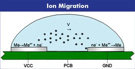
Challenge 2: Electrochemical Migration in Marine PCBs
Electrochemical migration occurs when a voltage bias exists between adjacent conductors in the presence of moisture and ionic contaminants. Metal ions dissolve from the anode, migrate through the electrolyte, and deposit at the cathode, forming conductive filaments that eventually bridge the gap. Marine conditions accelerate this process because salt dramatically increases conductivity. Proper spacing rules, avoidance of sharp corners in copper geometry, and control of bias voltages during design help limit migration risk. Reference to IPC-6012E qualification criteria guides acceptable spacing and cleanliness levels for such environments.
Challenge 3: Conformal Coating Failures in Marine Applications
Conformal coatings protect boards yet can fail through pinholes, poor adhesion, or cracking under thermal cycling combined with salt exposure. Once breached, the coating traps moisture and salts against the board surface, creating localized corrosion cells. Marine vibration and flexing further stress coating interfaces, especially around component leads and connectors. Selection of coating chemistries with proven adhesion to the chosen solder mask and substrate, together with controlled application thickness, improves long-term barrier performance.
Challenge 4: Galvanic Corrosion Between Dissimilar Metals
Marine PCBs often incorporate copper, tin, silver, and gold finishes along with various component terminations. When these metals contact an electrolyte, the more anodic material corrodes preferentially. Saltwater provides an excellent electrolyte, and temperature gradients drive continued ion movement. Design practices that minimize mixed-metal interfaces, apply consistent surface finishes across the board, and isolate dissimilar metals electrically reduce galvanic cell formation.
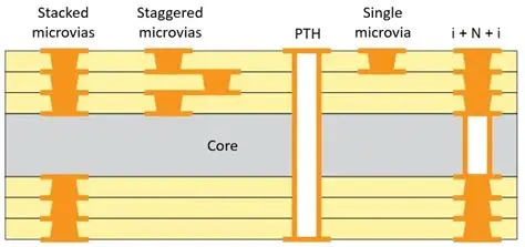
Challenge 5: Corrosion in Vias, Holes, and Under Components
Plated through-holes and blind vias trap moisture and salts that are difficult to remove during cleaning. Under large components or within dense connector arrays, airflow is restricted, allowing condensation to persist. Over repeated thermal cycles the trapped electrolyte drives pitting and barrel corrosion inside vias, increasing resistance or causing opens. Thorough cleaning processes validated against IPC-A-600K acceptability criteria, combined with via fill or tenting strategies where appropriate, limit entrapment.
Practical Solutions and Best Practices
Engineers begin by specifying laminates with low moisture absorption and high glass transition temperatures suited to marine thermal profiles. Surface finishes such as immersion silver or electroless nickel immersion gold provide better corrosion resistance than bare copper when properly applied. Controlled impedance routing and increased trace spacing further reduce migration risk. After assembly, ionic contamination testing confirms cleanliness before coating. Multiple thin coating layers with intermediate curing steps improve coverage compared with a single thick application. Periodic inspection protocols during service life allow early detection of coating degradation or salt buildup.
Conclusion
Marine PCB reliability depends on addressing salt ingress, electrochemical migration, coating integrity, galvanic couples, and entrapment sites through integrated design and process controls. Adherence to IPC-6012E and IPC-A-600K requirements during qualification provides a consistent framework for evaluating these measures. When these practices are applied systematically, boards achieve extended service life in harsh saltwater environments.
FAQs
Q1: What causes PCB corrosion in saltwater environments?
A1: Saltwater introduces conductive ions that lower insulation resistance and drive electrochemical reactions on copper and solder surfaces. Continuous humidity and temperature cycling keep the ions active, accelerating material loss and electrical degradation. Marine PCB corrosion prevention therefore focuses on blocking ion pathways and selecting resistant materials from the design stage.
Q2: How does electrochemical migration affect marine PCBs?
A2: Electrochemical migration forms conductive filaments between biased conductors when moisture and salts are present. The process increases leakage current and eventually creates short circuits. Design rules that maintain adequate spacing and control bias voltages, verified against IPC-6012E criteria, reduce the likelihood of migration in marine service.
Q3: Why do conformal coatings fail in marine applications?
A3: Conformal coating failures in marine environments stem from pinholes, poor adhesion after thermal shock, and mechanical stress from vibration. Once compromised, the coating can trap salts against the board, worsening corrosion. Proper surface preparation, compatible chemistry selection, and validated application thickness improve coating durability.
Q4: Which materials improve corrosion resistance for marine PCBs?
A4: Corrosion-resistant PCB materials include laminates with low moisture absorption, stable surface finishes such as immersion silver, and solder masks formulated for high adhesion. Combined with controlled cleaning and coating processes, these choices limit ion migration and galvanic activity in saltwater conditions.
References
IPC-6012E — Qualification and Performance Specification for Rigid Printed Boards. IPC, 2017
IPC-A-600K — Acceptability of Printed Boards. IPC, 2020