 ALLPCB


Introduction
Portable electronics and wearable devices have become increasingly common. As the wearable market grows, improving the accuracy of on-board fuel gauges is an important design challenge. Traditional built-in fuel gauges typically offer accuracy around ±8%. For example, when an indicator shows 10% remaining, the actual state of charge could be as low as 2%, causing unexpected shutdowns and potential data loss. In safety-critical applications such as medical devices, inaccurate remaining-time estimates could have serious consequences.
Adding discrete metering components can improve accuracy but may increase device size and weight. Because consumer demand favors thinner, more integrated wearables, designers must weigh accuracy improvements against component count, power consumption, and board area.
1. Traditional Method: Coulomb Counting
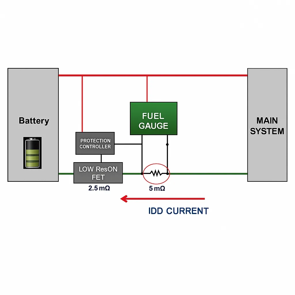
Coulomb counting is the most common fuel-gauge method. It uses a high-precision current-sensing resistor to continuously monitor battery output current. Current is integrated over time and compared with the known full capacity to estimate remaining charge.
The main drawback of coulomb counting is accumulated inaccuracy and the risk of unexpected shutdown. Self-discharge current does not flow through the external sense resistor, so it is not detected. Self-discharge varies with temperature, and heat generated during discharge can further change measurements. Accurate coulomb counting also typically requires the battery to be fully charged during calibration, which is not always the case in real use.
In addition, using a sense resistor increases cost and consumes PCB area. Current-sensing losses through the resistor reduce battery efficiency and increase power dissipation.
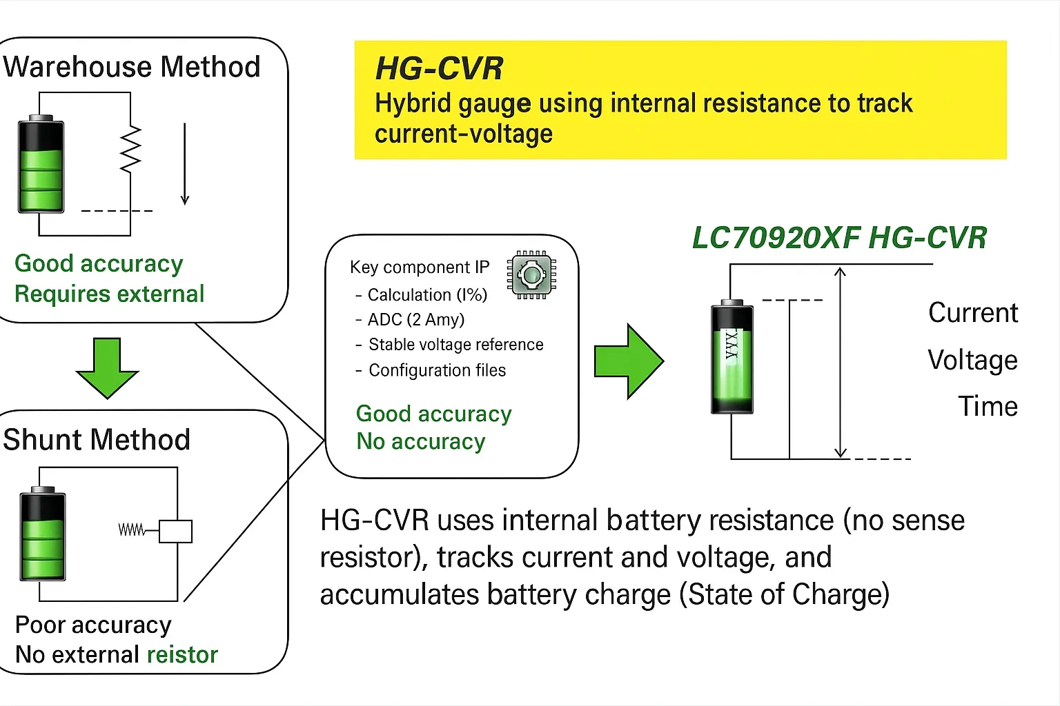
2. Hybrid Method: Internal Resistance Tracking of Voltage and Current (HG-CVR)
ON Semiconductor's LC70920XF smart lithium-ion fuel gauge addresses several limitations of coulomb counting by using an on-board fuel gauge based on precise ADC measurements together with error correction and temperature compensation. Because it eliminates the need for an external sense resistor, the solution reduces power loss and saves PCB area while supporting low-power operation and higher measurement precision.
The LC70920XF implements a method called HG-CVR. It reports relative state of charge (RSOC) with a typical error within ±2.8% under a range of conditions, including variations in temperature, aging, load, and self-discharge.
A precise internal reference voltage is critical for accurate voltage measurement. The device includes an accurate internal reference voltage circuit that is stable across temperature. It stores reference tables that include mappings of voltage/capacity, resistance/capacity, and resistance/temperature for the target battery.
The HG-CVR method measures cell voltage, temperature, internal resistance, and open-circuit voltage (OCV). OCV is the battery voltage with no load. The measured battery voltage is decomposed into OCV and the voltage change that results from load current and internal resistance. The current is estimated as:
V(VARIED) = V(MEASURED) - OCV
I = V(VARIED) / R(INTERNAL)
Here V(VARIED) is the voltage change due to load current, V(MEASURED) is the measured voltage, and R(INTERNAL) is the battery internal resistance. Internal resistance depends on remaining capacity, load, temperature, and other factors. After monitoring voltage, HG-CVR extracts charge (coulombs) and computes RSOC using resistance and voltage configuration tables.
Residual battery capacity is then computed by continuously comparing measured voltage and temperature against the stored reference tables. When the battery voltage is low, sampling becomes more frequent to maintain accuracy as remaining runtime decreases.
Unlike other charge measurement methods, HG-CVR can account for self-discharge events and does not require a full charge cycle for calibration. Even when the battery is charged to only 50%, HG-CVR can estimate remaining runtime accurately.
3. Detecting Battery Aging
Repeated charge/discharge cycles increase internal resistance and reduce full charge capacity (FCC). In coulomb counting, FCC and remaining capacity (RM) are used to compute RSOC:
RSOC = RM / FCC × 100%
Coulomb counting typically requires learning cycles to measure reduced FCC. HG-CVR can report RSOC without such learning cycles because it estimates internal resistance and correlates that to FCC. The correlation depends on battery chemistry; using it allows RSOC estimation that is less affected by aging.
4. Error Auto-Convergence
An inherent problem with coulomb counting is error accumulation over time; it requires opportunities for recalibration. The LC70920XF’s HG-CVR implementation supports RSOC error convergence by continually refining OCV estimates. Small changes in remaining capacity due to self-discharge that are too small for coulomb counting to detect can be captured by HG-CVR using voltage information.
5. Simplified Integration
Collecting multiple battery parameters usually requires additional measurement circuitry and development time. The LC70920XF includes multiple configuration tables internally, which reduces the amount of external configuration required at startup, simplifying design and speeding integration.
6. Power-On Reset and Battery Insertion Detection
When the LC70920XF detects battery insertion it performs an automatic power-on reset. Once battery voltage exceeds the reset release voltage (VRR), the device leaves reset and completes initialization before entering sleep or operating mode. All registers are initialized after power-on reset. If battery voltage drops significantly below VRR during operation, the device can perform a system reset.
7. Low Power
HG-CVR measures voltage and temperature at preset intervals rather than continuously. This allows the gauge to enter a low-power sleep mode between measurements and reduces active power consumption because no external sense resistor is required.
By reducing required external components, HG-CVR implementations can lower overall power consumption. For example, the LC709203F reduces external component count compared with some competing solutions, eliminates the external current-sense resistor, and is offered in compact packages (1.76 mm × 1.6 mm for one package option). The device claims lower board area and lower typical operating current. Reported operating current figures are on the order of 15 μA in active mode compared to higher currents for some competing solutions, and significantly lower sleep current.
8. Temperature Compensation
Lithium-ion batteries are sensitive to environmental conditions and temperature. As temperature falls below 0°C, internal resistance changes and voltage drop under load increases. The LC70920XF includes internal compensation algorithms to maintain reported error within approximately ±2.8% across a wide temperature range and across typical battery voltages.
9. LC709203F Smart Fuel Gauge Overview
Functional highlights:
- HG-CVR algorithm: measures RSOC without external sense resistor; reported RSOC error typically within 2.8%; accounts for parasitic resistance to simplify design.
- Low power operation.
- Precision voltage measurement with an accurate internal reference.
- Built-in timers.
- Alerts for low RSOC or low voltage.
- Temperature compensation: temperature can be supplied via an I2C input or measured directly with a thermistor. Temperature compensation helps keep error within specified limits across a wide range of temperatures and voltages.
- I2C interface supports up to 400 kHz.
Key electrical parameters (representative):
- Operating current, normal mode: VDD = 2.5 to 4.5 V; typical 15 μA; maximum 26 μA.
- Sleep mode current: VDD = 2.5 to 4.5 V; typical 0.2 μA; maximum 4 μA.
- Voltage measurement accuracy: at Ta = +25°C, typical accuracy is within ±7.5 mV per cell; over Ta = -20°C to +70°C and VDD = 2.5 to 4.5 V, accuracy is within approximately ±20 mV per cell.
Module Diagram and Pin Assignment
The LC709203F is available in WDFN8 and WLCSP9 packages. Key pin descriptions:
- TEST: connect to VSS.
- VSS: battery negative.
- VDD: battery positive.
- ALARM (ALARMB): open-drain alarm output. An external pull-up is required. Alarm conditions are register-configurable. When not used, the pin should be tied to VSS. If battery charge falls below a threshold, an internal open-drain FET will pull the ALARMB output low.
- TSW: thermistor supply output. This pin goes high when reading temperature. The TSW pull-up resistor must match the thermistor used.
- TSENSE: thermistor input. If a thermistor is connected to this pin, insert a 100 Ω resistor in series for ESD protection.
- SDA: I2C data pin (open drain). External pull-up required.
- SCL: I2C clock pin (open drain). External pull-up required.
Layout and Electrical Considerations
- I2C address is fixed; ensure no other devices share the same address on the bus.
- Initialization after power-up is typically within 80 ms.
- If RSOC is initialized via I2C, battery readings are available after approximately 2 ms.
- When power is applied to VDD and VSS, battery readings remain valid regardless of register enable/disable state.
- Place a decoupling capacitor (1 μF) close to the IC between VDD and VSS.
- If the alarm function is not used, tie the alarm output to VSS; no pull-up is required.
Summary
Wearable devices benefit from fuel gauges that offer higher accuracy, smaller size, and low power. Implementations based on internal voltage, temperature, and internal-resistance tracking, such as HG-CVR, address many limitations of coulomb-counting approaches by including error correction and temperature compensation. Eliminating the external sense resistor reduces component count, board area, and power losses, while on-board configuration tables simplify integration and improve reported state-of-charge accuracy under real-world conditions.


