ALLPCB


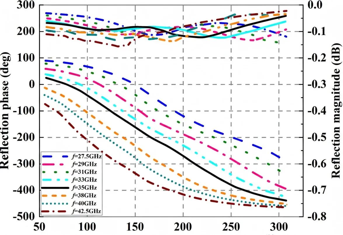
This study presents a single-layer windmill-type unit cell designed to broaden the bandwidth of a reflectarray antenna. To obtain a sufficiently wide phase range, a windmill-ring patch and a circular-ring patch are used to achieve multiple resonant states. The proposed unit achieved a linear phase-shift curve with a 473.6° phase range in HFSS simulation. Across 27.5 GHz to 42.5 GHz, most phase-shift curves remain parallel, indicating broadband behavior. Based on this unit, a single-layer offset-fed prototype with a square aperture of 80 mm x 80 mm and 400 elements was designed, simulated, fabricated, and tested. Detailed measurements show a peak gain of 27.86 dBi and an aperture efficiency of 51.7% at 37 GHz. The 3 dB gain bandwidth measured is 35.71% (27.5 GHz–40 GHz).
Background
For high-gain antennas, reflectarray antennas combine advantages of parabolic reflectors and phased arrays and are a suitable candidate for 5G systems. Due to large apertures and spatial feed methods, reflectarrays can radiate high-gain pencil beams by adjusting surface element structures. However, narrow bandwidth limits reflectarray application in communication systems. Efforts to broaden reflectarray bandwidth commonly use multilayer and single-layer multi-resonant techniques. Multilayer multi-resonant techniques use two or more dielectric layers to form multiple resonant points; optimizing multilayer patch parameters can adjust phase linearity and range, but this increases manufacturing complexity and cost and can introduce alignment errors. Single-layer multi-resonant techniques can achieve similar results using a low-profile, low-cost single dielectric substrate. This study uses a single-layer multi-resonant technique to construct a wideband reflectarray.
Reflectarray Design Workflow
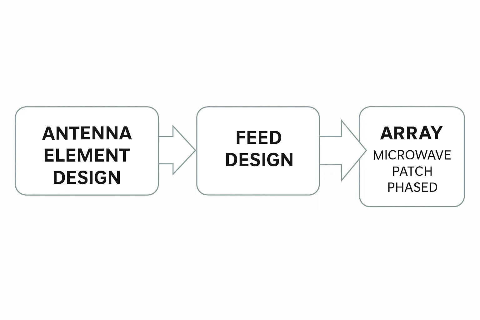
For a reflectarray antenna, the design generally includes the following three basic steps:
Unit Design
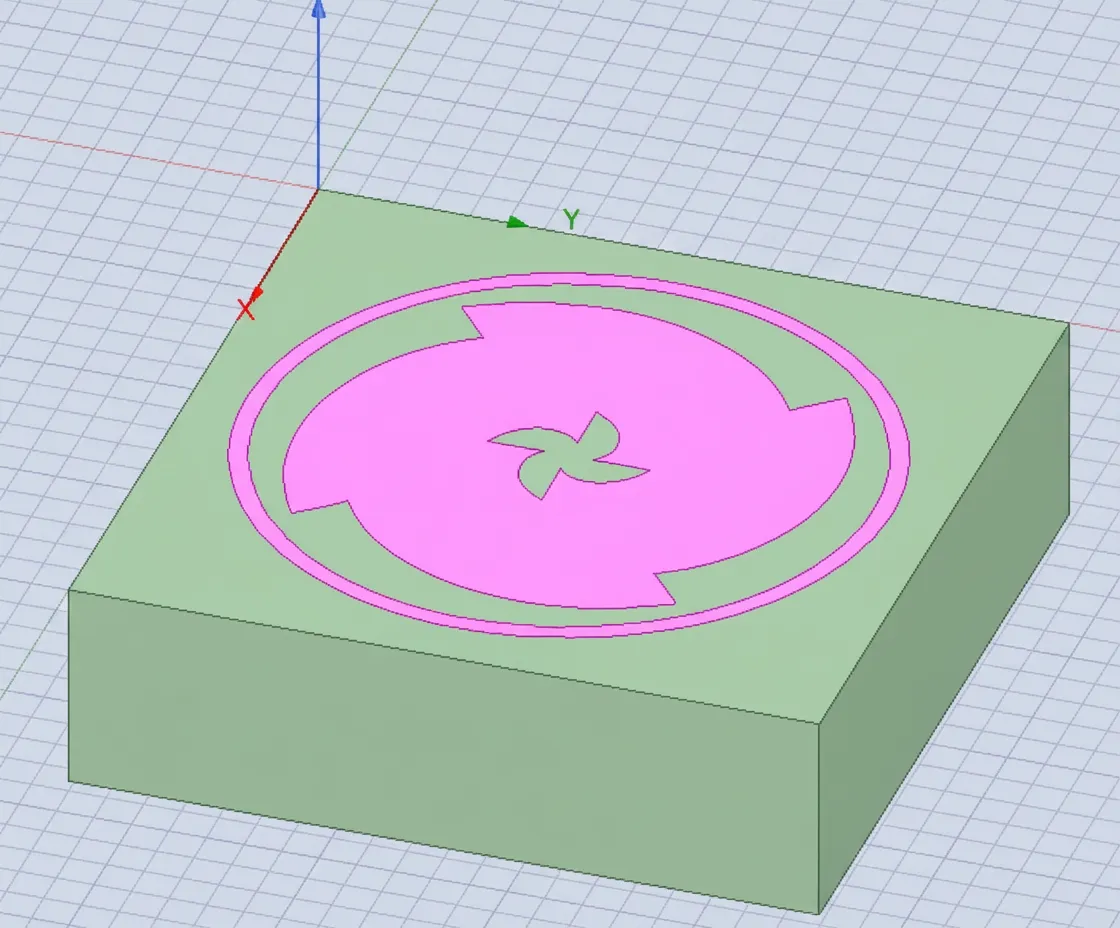
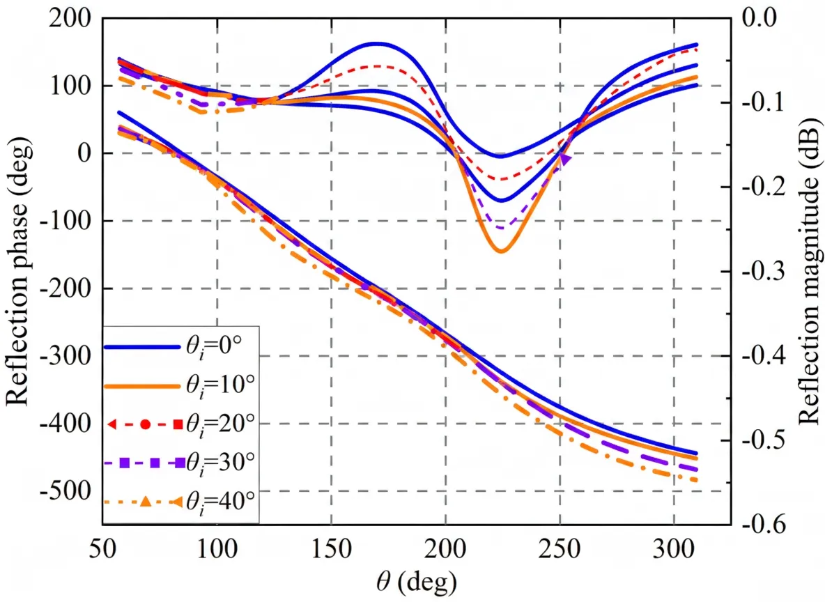
This study proposes a hybrid phase-tuning unit combining dimension-varying and rotation-type mechanisms, shown in Figure 1. The size and orientation of the windmill-ring patch change simultaneously with θ. When the circular-ring patch and the windmill-ring patch reach resonant sizes, dual resonances occur, extending the phase range. The proposed unit is a hybrid phase-shift structure that uses both resonant and geometric phase modulation. When θ varies from 57.6° to 309.6°, the unit achieves a 473.6° phase-shift range at 35 GHz with low loss, demonstrating full phase coverage and a highly linear reflection phase curve, as shown in Figure 2. This linearity is an important factor for broadband performance.
To ensure good radiating performance for the reflectarray, the effect of incidence angle on the unit reflection properties was analyzed, as shown in Figure 3. When the incidence angle θi changes from 0° to 40°, the reflection phase and magnitude change little, indicating insensitivity to incidence angle. As shown in Figure 4, across the 27.5 GHz to 40 GHz range, the variation in phase deviation is also small, indicating stable phase-shift curves over a wide bandwidth.
Feed Design
The design uses a linearly polarized conical horn in the Ka-band. HFSS was used to determine the horn phase center. To ensure efficient illumination of the array and reduce blockage between the feed and the reflectarray, the vertical distance between the feed phase center and the reflectarray is 80 mm (F/D = 1), and the angle between the incident and reflected beams at the reflectarray center is set to 15°.
Array Assembly
With the unit and feed prepared, the required compensating phase for each array element is computed so that the incident beam reflected by the reflectarray forms the desired beam direction. The calculation uses:
where k0 is the propagation constant in free space. The distance between the feed phase center and the center of the n-th element is denoted as dmn, r0 is the unit vector of the main beam, and rmn is the position vector of element mn. Combining the unit phase-shift curves and using MATLAB, the required element sizes were obtained.
Finally, using the computed element sizes, automated modeling was implemented through co-simulation of MATLAB and HFSS. The overall antenna structure is shown in Figure 5. To validate HFSS simulations, a prototype was fabricated and tested; photos are shown in Figure 6. Measured results closely match simulations, as shown in Figure 7. The measured peak gain is 27.86 dBi at 37 GHz, with an aperture efficiency of 51.7%. Simulations indicate that gain variation is less than 3 dB from 27.5 GHz to 42.5 GHz (relative bandwidth 42.86%). However, due to the VNA frequency limit, measurements were limited to 40 GHz, yielding a measured 3 dB gain bandwidth of 35.71% (27.5 GHz–40 GHz).
Conclusion
This study proposed a novel windmill unit composed of a circular-ring patch and a windmill-ring patch with a hybrid phase-tuning mechanism. HFSS optimization produced a linear phase-shift curve covering 473.6°. Based on this unit, an 80 mm x 80 mm single-layer Ka-band offset-fed sample was designed, fabricated, and tested. Measured results show a peak gain of 27.86 dBi and an aperture efficiency of 51.7%, in good agreement with simulations.