ALLPCB


Overview
Cellular base stations are integrated into daily life like water and electricity, but many users do not fully understand their internal components. This article explains one of the most important base station components: the remote radio unit, or RRU.
1. What is an RRU?
An RRU (Remote Radio Unit) is one of the two core elements of modern base stations, alongside the BBU (baseband unit). Historically, early base stations used an integrated design where baseband and RF modules were combined in a single enclosure. That design introduced several disadvantages that prompted the move to a distributed architecture with separate BBUs and RRUs.
Problems with Integrated Base Stations
Integrated base stations have several drawbacks:
- Large feeder loss. The base station had to be installed at the tower base and use long RF feeder cables to deliver signal to antennas mounted tens or hundreds of meters above. Feedline attenuation is significant; for example, a common 7/8 feeder at 900 MHz loses about 4 dB per 100 meters. If the antenna input needs 100 W, the transmitter might need to supply 250 W at the base to overcome feeder loss, which increases power consumption substantially.
- High power consumption. Because of feedline loss and limited RF amplifier efficiency, an integrated site requires much higher transmit power. Using the earlier example and assuming 30% PA efficiency, a single PA module could consume several hundred watts, and a full site with three sectors can easily exceed 3 kW, not counting additional equipment or multiple frequency bands.
- Cooling challenges. A high-heat integrated unit in a small equipment room requires high-capacity fans and air conditioning, increasing noise and power draw and reducing reliability.
- Difficulty supporting advanced air interfaces. In 4G and later systems, multi-antenna configurations such as 4x4 MIMO or 8 ports require many more feeder cables and additional combiners/splitters, raising insertion loss and cost.
2. Emergence of the RRU
To address these issues, baseband and RF functions were separated into two modules: the BBU and the RRU, connected by fiber. The RRU is installed near the antenna at the tower top while the BBU remains in the equipment room at the tower base. Because the RF jumpers between RRU and antenna are very short, feeder loss is negligible, enabling lower transmit power and improved overall efficiency.
RRUs are typically weatherproof and designed with passive-finned enclosures for natural convection cooling, eliminating the need for fans and improving reliability. The separation also enables flexible deployment: BBUs can be located many kilometers away from RRUs, which made centralized RAN architectures such as C-RAN possible, where BBUs are pooled in a central facility and manage multiple distant RRUs.
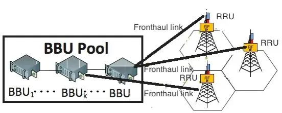
C-RAN network architecture
3. Key RRU Metrics
To evaluate an RRU, the most relevant technical metrics include:
- Supported frequency bands. Defined ranges for FDD and TDD operation. For example, FDD 900 MHz (4G Band 8, 5G n8) has downlink 925–960 MHz and uplink 880–915 MHz. TDD 3.5 GHz (5G n78) covers 3.3–3.8 GHz. Some RRUs are ultrawideband (UBR) and can support multiple bands simultaneously, reducing the number of RRUs and antenna ports required.
- Operating bandwidth (often called operational bandwidth). Due to implementation cost, an RRU typically supports a portion of a standardized band determined by internal filter passbands. For example, the FDD 1800 MHz band (75 MHz) may be implemented with two RRU variants whose downlink operational bands overlap but are narrower.
- Instantaneous bandwidth (IBW). The maximum contiguous or noncontiguous bandwidth the RRU can transmit or receive simultaneously. The actual instantaneous bandwidth in use depends on operator spectrum allocation. For 4G an operator might have a 20 MHz carrier, so IBW would be 20 MHz. For 5G, IBW requirements are larger, commonly in the 200–400 MHz range.
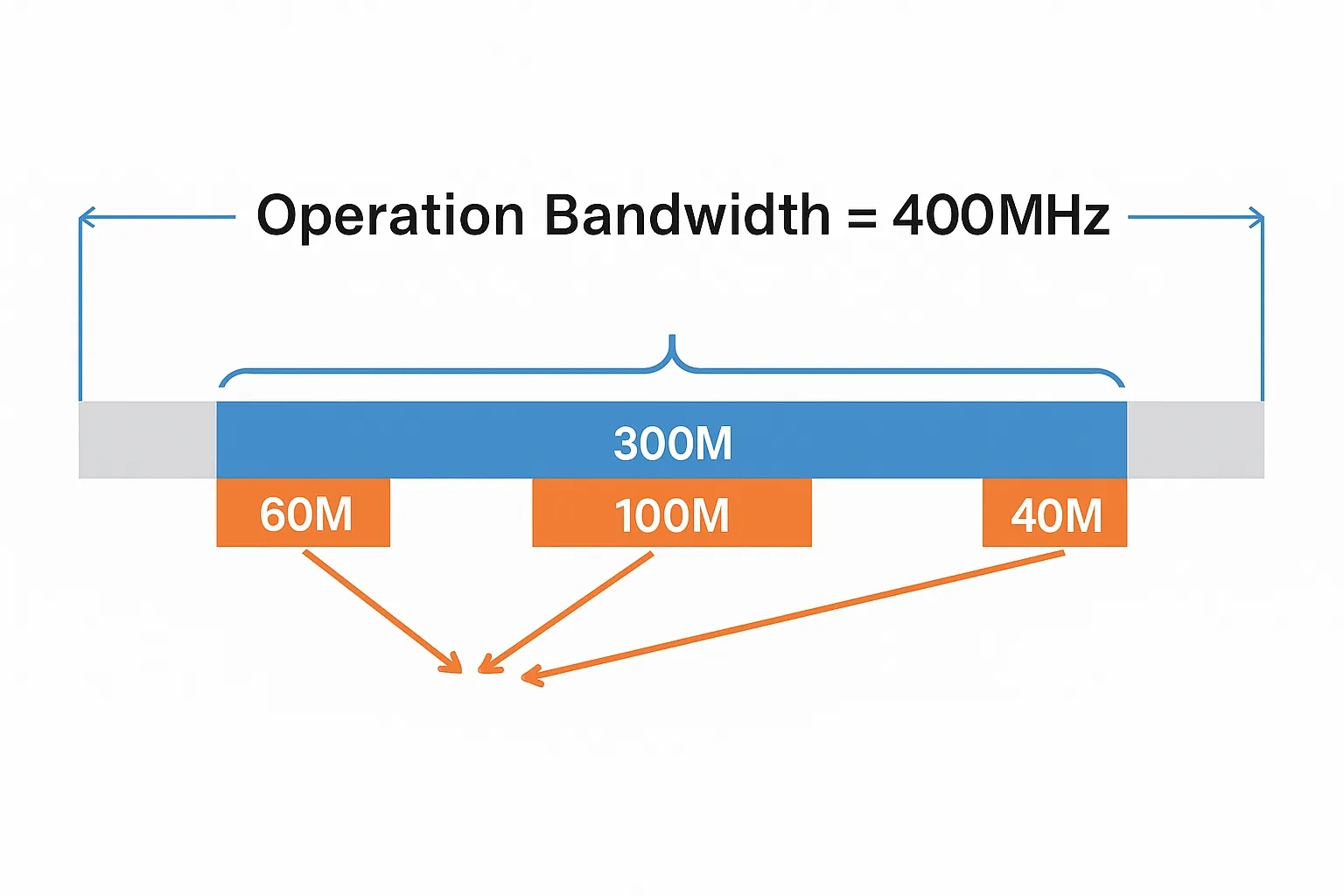
- Occupied bandwidth (OBW). The sum of actual used transmit bandwidth within the IBW. When transmit bandwidths are noncontiguous, OBW indicates the aggregate used bandwidth. For example, an RRU with a 300 MHz IBW and 200 MHz OBW can allocate that 200 MHz as one continuous block or as several noncontiguous blocks whose total bandwidth does not exceed 200 MHz and whose span fits within the 300 MHz IBW.
- Capacity. The number of 2G/3G/4G/5G sectors or cells an RRU can support. Capacity reflects a trade-off between technical capability and cost. From an operator perspective, higher capacity reduces the need for hardware upgrades and can be enabled via software when feasible.
- Tx/Rx port count. The number of transmit and receive ports used to connect antennas. This determines support for MIMO configurations, beamforming capabilities, and uplink reception diversity. A typical 4G RRU might be 4T4R (four Tx/Rx ports), supporting up to 4x4 MIMO downlink and 4-stream uplink diversity.
- Maximum rooftop transmit power. The maximum aggregate transmit power the RRU supports. Modern RRUs often need to handle multiple radio access technologies on the same band; for example, 900 MHz RRUs may need to support 2G, 3G, 4G, and NB-IoT simultaneously, requiring 120 W or even 160 W total. If power is distributed over multiple ports, this is specified as, for example, 4x40 W. For 5G, wider bandwidths often require higher aggregate transmit powers, frequently in the 200–300 W range.
- Average and peak power consumption. Average consumption reflects typical operating conditions; peak consumption corresponds to full-power transmission. Power consumption depends on operating modes, hardware design, and software algorithms, and is a key factor for operators because lower power reduces operational cost and may avoid upgrades to site power delivery infrastructure.
- Receive sensitivity. The minimum uplink signal level the RRU can reliably detect, which is critical for uplink coverage because user devices transmit at relatively low power. For example, 4G specifications require about -101.6 dBm sensitivity for a 20 MHz carrier, which corresponds to roughly 690 pW.
RRUs transformed base station architecture by moving RF functionality to the tower top and improving efficiency, coverage, and deployment flexibility. With the evolution to 5G, RRUs continue to evolve toward integrated active antenna units (AAUs) that combine antenna elements and active RF functions into a single unit.