 ALLPCB


Introduction
Selective soldering stands out as a precise method for assembling through-hole components on mixed-technology printed circuit boards, where surface-mount devices already occupy much of the board real estate. This process targets specific areas, minimizing heat exposure to sensitive parts and reducing the risk of defects common in full-wave soldering. Optimizing selective soldering parameters ensures reliable solder joints that meet performance demands in demanding applications. Engineers often face challenges like incomplete wetting, bridging, or thermal stress, making parameter control essential for high yields. By focusing on factors such as selective soldering parameters, including solder nozzle design and flux application, manufacturers can achieve consistent results. This article explores these elements with practical insights for troubleshooting and refinement.
What Is Selective Soldering and Why It Matters
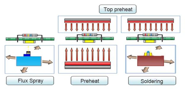
Selective soldering involves a multi-step sequence: flux deposition on targeted through-hole leads, preheating the assembly, and then immersing or dragging the joints through a localized solder wave via a specialized nozzle. Unlike reflow or traditional wave soldering, it allows programmable paths for each connector or component, ideal for high-density boards. This technique matters because modern electronics feature hybrid assemblies where through-hole parts like connectors demand robust mechanical strength not always achievable with surface-mount alternatives. Poorly optimized processes lead to issues such as solder skips, icicles, or joint voids, compromising reliability under vibration or thermal cycling. Adhering to standards like IPC J-STD-001 for soldering requirements helps define acceptable joint criteria, guiding parameter adjustments. For electric engineers, mastering selective soldering parameters translates to fewer rework cycles and faster time-to-market.
Understanding the Core Technical Principles
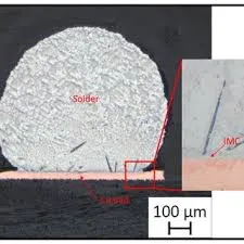
The foundation of selective soldering lies in achieving proper wetting, where molten solder flows into vias and around leads without contaminating neighboring areas. Flux plays a pivotal role by removing oxides and promoting alloy formation, but its interaction with preheat temperature dictates activation. Preheating, often in multiple zones, brings the board close to the solder's liquidus point, reducing delta-T shock that could warp boards or damage components. Solder nozzle geometry influences wave height, contact uniformity, and dross formation, directly affecting fill rates in plated-through holes. Nitrogen atmosphere minimizes oxidation at the solder-pot interface, preserving alloy purity and joint cosmetics. Dwell time, the duration of solder contact, ensures complete capillary action, critical for high-aspect-ratio holes.
Engineers must consider thermal mass variations across the board, as thicker copper planes or dense ground fills demand adjusted selective soldering parameters to avoid cold joints. Process simulation tools can model heat transfer, but real-world profiling per IPC-7530 guidelines verifies profiles. Flux volatility under heat influences residue levels, potentially causing electrical shorts if not managed. Nozzle wear over time alters immersion depth, necessitating regular inspections. Balancing these mechanisms prevents common pitfalls like meniscus bridging between pins.
Key Selective Soldering Parameters Explained
Solder Nozzle Selection and Optimization
The solder nozzle defines the process window by controlling solder volume delivery and contact precision. Wettable nozzles, typically made from specialized alloys, maintain a stable wave shape during dip or drag modes. For fine-pitch connectors, narrower nozzles with optimized apertures prevent solder overflow onto adjacent pads. Larger nozzles suit bulky components but risk shadowing smaller leads nearby. Immersion depth, usually a fraction of nozzle diameter, requires calibration to achieve 75-100% hole fill without excess solder balls.
Troubleshooting nozzle issues starts with matching geometry to lead span; mismatched sizes cause incomplete wetting or bridging. Regular cleaning removes dross buildup, which disrupts flow. In high-volume runs, programmable nozzle swaps enhance flexibility. Monitoring wave height via sensors ensures repeatability, aligning with IPC-A-610 acceptability criteria for joint appearance.
Soldering Temperature Control
Soldering temperature must exceed the alloy's liquidus point sufficiently for fluid flow while avoiding overheating that degrades flux or causes intermetallic growth. Pot stability prevents fluctuations leading to inconsistent joints. Preheat complements pot temperature, creating a ramp that activates flux without boiling it prematurely. Thermal profiling captures peak temperatures and times above liquidus, essential for process validation.
Excessive temperature promotes dross and oxidation, while insufficient values yield rough fillets. Engineers adjust based on alloy type, board thickness, and hole aspect ratio. Closed-loop controls maintain setpoints, reducing variability. Integration with nitrogen reduces oxygen-related temperature spikes at the surface.
Flux Application Techniques
Flux application demands precision to coat leads and barrels uniformly without pooling or splatter. Drop-jet systems offer pinpoint accuracy over spray fluxers, minimizing overspray on bottom-side SMDs. Viscosity and solids content influence coverage; low-solids fluxes reduce residue but require robust activation. Volume per joint, often microliter-range, balances wetting promotion against bridging risk.
In troubleshooting, uneven flux leads to skips; verify droplet size and standoff height. Post-flux preheat evaporates solvents, enhancing tackiness. Compatibility with no-clean processes avoids cleaning steps. Standards like IPC J-STD-001 specify flux performance in joint formation.
Dwell Time and Contact Dynamics
Dwell time governs solder penetration into capillaries, typically longer for drag soldering than dip. It includes approach, immersion, and withdrawal phases, optimized via motion programming. Short dwells risk voids from trapped flux; extended ones invite skulling on leads. High thermal mass demands 2-5 seconds per joint cluster.
Adjustments counter board warpage or lead coplanarity issues. Synchronization with travel speed refines effective contact. Profiling dwell against fill percentage quantifies optimization.
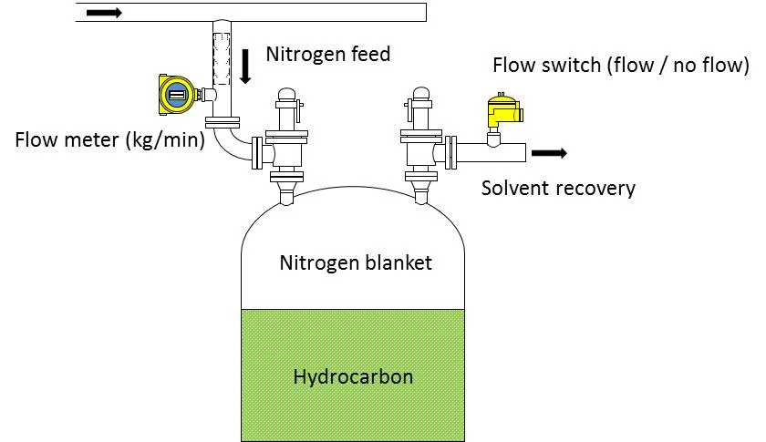
Nitrogen Atmosphere Benefits
Nitrogen purges oxygen around the nozzle, curbing dross, improving wetting speed, and yielding shinier joints. Flow rate and hood enclosure determine efficacy; low levels suffice for cosmetics, higher for high-reliability. It lowers required temperatures, easing thermal budgets.
Troubleshooting oxidation shows as matte joints or balls; boost purity to 99.999%. Cost-benefit favors it for lead-free alloys.
Best Practices for Process Optimization
Start with design-for-selectivity: panelize boards for fixturing, specify lead protrusions per IPC guidelines. Develop a parameter matrix testing nozzle size against dwell for baseline yields. Implement SPC on joint metrics like hole fill via cross-sections. Preheat multi-zone setups for gradient control, targeting topside temperatures for flux life.
Daily verifications include pot thermocouple checks and fluxer calibration. Nitrogen purity logs prevent drift. For troubleshooting, root-cause via DOE: vary one selective soldering parameter at a time. Simulate high-mass scenarios with drop-in heaters. Post-solder inspection per IPC-A-610 catches defects early.
Software programming optimizes paths, minimizing travel time without collisions. Operator training on anomaly recognition boosts consistency. Scaling to production iterates parameters with yield data.
Common Troubleshooting Scenarios
Bridging often stems from flux excess or nozzle too wide; reduce volume or switch to parallel drag. Voids trace to air entrapment; extend dwell or use nitrogen vigorously. Skull joints indicate low temperature or short contact; profile and adjust. Warpage from uneven preheat requires fixturing or dual zones.
Solder skips signal poor fluxing; inspect standoff and pump pressure. Matte appearance points to oxidation; verify nitrogen seals. Systematic logging correlates defects to parameters for predictive fixes.
Conclusion
Optimizing selective soldering parameters unlocks defect-free assemblies, blending precision flux application, stable soldering temperature, tailored solder nozzles, adequate dwell time, and nitrogen atmosphere. Practical command of these yields robust joints meeting IPC standards. Engineers gain efficiency through profiling, monitoring, and iterative refinement. Prioritize process control for reliability in evolving electronics demands.
FAQs
Q1: What are the most critical selective soldering parameters for high-yield production?
A1: Flux application uniformity, solder nozzle geometry, and dwell time top the list, as they directly impact wetting and fill. Preheat and soldering temperature ensure flux activation without degradation. Nitrogen atmosphere enhances consistency by reducing oxidation. Monitor via profiling to sustain IPC J-STD-001 compliance.
Q2: How does nitrogen atmosphere affect soldering temperature in selective processes?
A2: Nitrogen lowers oxidation, allowing slightly reduced soldering temperatures for the same wetting speed. It stabilizes the pot surface, minimizing dross and temperature fluctuations. This extends flux life and improves joint cosmetics. Balance flow to avoid turbulence disrupting the wave.
Q3: Why is dwell time a key selective soldering parameter for through-hole components?
A3: Dwell time facilitates solder flow into high-aspect holes, preventing voids from flux entrapment. Optimize based on lead pitch and thermal mass; too short causes incomplete fill, too long risks bridging. Programming precise paths refines it. Cross-section analysis verifies effectiveness.
Q4: How to troubleshoot flux application issues in selective soldering?
A4: Check droplet volume and height for uniform coverage; excess causes bridging, deficiency leads to skips. Preheat verifies activation without splatter. Switch to drop-jet for precision. Correlate with joint quality per IPC-A-610.
References
IPC J-STD-001 — Requirements for Soldered Electrical and Electronic Assemblies. IPC
IPC-A-610 — Acceptability of Electronic Assemblies. IPC
IPC-7530 — Guidelines for Temperature Profiling. IPC


