 ALLPCB


Introduction
Manual assembly of electronics offers hobbyists a hands-on way to bring projects to life without relying on automated machinery. From building custom circuits to prototyping Arduino shields, having the right tools ensures reliable results and reduces frustration during the process. This guide covers a comprehensive manual assembly tools list tailored for electronic hobbyists, focusing on essentials that deliver precision and safety. Whether you are populating a simple PCB or tackling through-hole components, these tools form the foundation of successful hand assembly. Understanding their roles helps avoid common pitfalls like poor joints or component damage.
Key categories include soldering equipment, precision handling tools, inspection aids, and ESD protection. Each plays a critical part in achieving professional-quality work at home. By selecting the best equipment for hand assembly, hobbyists can match industry expectations while enjoying the creative process.
Why Manual Assembly Matters for Hobbyists
Manual assembly empowers hobbyists to experiment freely, learn soldering techniques, and customize projects on a budget. Unlike surface-mount technology lines in factories, hand methods allow immediate fixes and iterations without setup costs. It builds skills essential for troubleshooting real-world electronics, such as identifying cold solder joints or bent leads. For beginners, starting with manual tools fosters confidence before scaling to complex boards.
This approach aligns with standards like J-STD-001, which outlines requirements for soldered electrical assemblies, ensuring hobbyist work meets basic reliability benchmarks. Reliability improves when tools match the task, preventing issues like overheating components. Hobbyists benefit from the tactile feedback that automation cannot replicate, honing intuition for component placement.
Essential Soldering Equipment
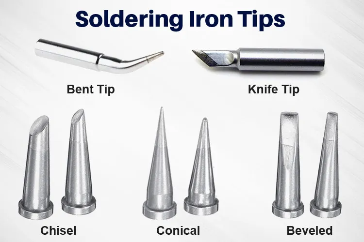
Soldering irons top any manual assembly tools list due to their versatility in joining components to boards. Temperature-controlled models prevent damage to sensitive parts by maintaining steady heat, typically adjustable from 300 to 450 degrees Celsius. Fine tips, such as conical or chisel shapes, suit through-hole and surface-mount work, allowing precise heat application. Pair the iron with thin solder wire, 0.5 to 1 mm diameter, containing 60/40 tin-lead or lead-free alloys for strong bonds.
Flux pens or paste enhance wetting, removing oxides for cleaner joints. Desoldering braids and pumps correct mistakes quickly, minimizing board stress. Always clean tips with a damp sponge or brass wool to sustain performance.
Soldering Iron Recommendations
Choose irons with ergonomic handles and quick heat-up times under 30 seconds for comfortable extended sessions. Digital displays help monitor temperature, crucial for delicate SMD components. Standby modes protect tips from oxidation during pauses. Quick-change tip systems add flexibility for varied pad sizes.
Precision Handling Tools
Tweezers for electronics rank high for their role in placing tiny resistors, capacitors, and ICs without fingerprints or scratches. Fine, straight or curved tips, under 0.1 mm at the end, grip parts securely during alignment. Anti-magnetic stainless steel construction avoids disturbing nearby components. Multiple sets cover tasks from SMD pickup to lead bending.
Wire cutters with flush edges trim leads close to the board, preventing shorts. Needle-nose pliers adjust pins on connectors precisely. Helping hands clamps hold boards steady, freeing both hands for soldering.
Inspection and Magnification Aids
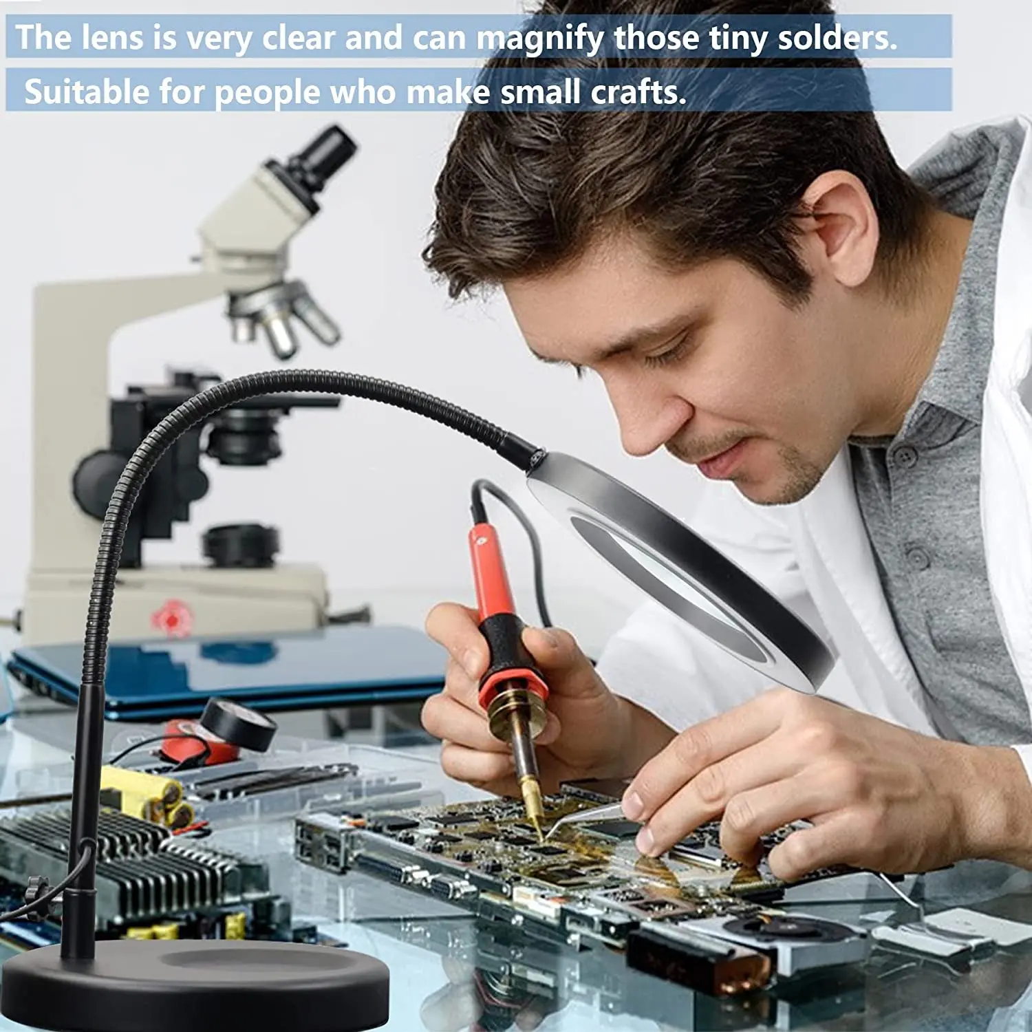
A magnifying glass for soldering reveals hidden defects like bridges or insufficient fill. 5x to 10x magnification with LED lighting illuminates work areas effectively. Head-mounted versions free hands for tweezers operation, ideal for prolonged sessions. Bench stands with adjustable arms position optics optimally over the PCB.
For finer details, opt for digital microscopes offering 50x to 200x zoom on screens. These tools confirm joint fillet shapes per IPC-A-610 acceptability criteria, spotting cracks early. Good lighting reduces eye strain during inspections.
ESD Safe Tools and Protection
ESD safe tools prevent electrostatic discharge from damaging semiconductors, a top concern in manual work. Wrist straps ground the user through coiled cords to mats, dissipating charges safely. Conductive mats cover workbenches, paired with ionizers to neutralize air particles. ESD bags store components, blocking static buildup.
Tools like tweezers and irons with dissipative handles integrate protection seamlessly. Following IEC 61340 guidelines for ESD control ensures hobbyist setups match professional standards. Test setups with meters to verify resistance paths under 1 megohm.
Additional Best Equipment for Hand Assembly
Multimeters verify continuity and voltages post-assembly, catching opens or shorts. Hot air rework stations remove stubborn SMDs without mechanical stress, using low airflow. Fume extractors capture lead vapors, promoting safe breathing. Solder paste stencils aid consistent SMD deposits for prototypes.
Storage organizers keep tools accessible, reducing search time. Alcohol swabs clean residues promptly.
Best Practices for Manual Assembly
Organize your station with tools within arm's reach to maintain workflow. Preheat boards gently if populated densely, avoiding thermal shock. Apply flux sparingly to pads and leads for optimal flow. Heat joints 2 to 3 seconds maximum, letting solder melt naturally.
Inspect each joint immediately under magnification, checking for shine and fillet. Clean flux residues with isopropyl alcohol to prevent corrosion. Document setups with photos for troubleshooting repeats.
Troubleshooting Common Assembly Issues
Poor wetting often stems from dirty tips or oxidized pads, resolved by fresh flux and tip tinning. Tombstoning in SMDs happens from uneven heating; slow iron ramps fix it. Bent leads under ICs require gentle plier straightening before insertion.
Cold joints appear dull; reheating with flux smooths them. ESD damage mimics opens; verify with scope if multimeter passes. Consistent practices per J-STD-001 minimize recurrences.
Conclusion
Mastering a solid manual assembly tools list transforms hobbyist projects into reliable electronics. From soldering iron recommendations to ESD safe tools, each piece contributes to quality outcomes. Tweezers for electronics, magnifying glass for soldering, and best equipment for hand assembly enable precise work matching industry standards. Invest time in setup and practices for frustration-free building. Experiment confidently, knowing these essentials support your creativity.
FAQs
Q1: What is a comprehensive manual assembly tools list for beginners?
A1: Start with a temperature-controlled soldering iron, fine tweezers for electronics, flush cutters, a magnifying glass for soldering, and an ESD mat with wrist strap. Add flux, solder wire, and helping hands for stability. These cover 90% of hand assembly needs, allowing progression from simple circuits to prototypes. Follow basic cleaning routines to extend tool life.
Q2: Which soldering iron recommendations suit electronic hobbyists?
A2: Opt for adjustable temperature models with fine tips and digital readouts for control. Quick heat-up and ergonomic grips support long sessions without fatigue. Pair with 0.7 mm solder for versatility across through-hole and SMD. This setup aligns with reliable joint formation principles.
Q3: Why are ESD safe tools essential in hand assembly?
A3: ESD safe tools like mats and straps protect sensitive chips from invisible discharges that cause failures. Hobbyists handle components directly, increasing risk without grounding. IEC 61340-compliant setups ensure static-free zones. Integrate them from the start for robust projects.
Q4: How does a magnifying glass for soldering improve results?
A4: It reveals microcracks, insufficient solder, or bridges invisible to the naked eye. LED-lit 5x to 10x models aid precise tweezers work on small pads. Inspections confirm IPC-A-610 joint acceptability. Reduced rework saves time and materials.





