 ALLPCB


Introduction
Deciding the right batch size in PCB assembly stands as a pivotal choice for engineers balancing production demands. Smaller batches often promise tighter quality control but drive up per-unit costs through repeated setups. Larger batches spread fixed expenses across more units, enhancing economic viability yet risking widespread defects if issues arise mid-run. Optimizing batch size requires weighing PCB assembly cost analysis against quality vs quantity trade-offs. Production efficiency hinges on this decision, influencing throughput, scrap rates, and delivery timelines. Engineers must grasp these dynamics to refine processes without compromising reliability.
Defining Batch Size in PCB Assembly
Batch size refers to the number of PCB assemblies processed consecutively in a single production run, from stencil printing through reflow soldering and final inspection. In surface-mount technology lines, it dictates how many panels or individual boards move together, affecting machine changeovers and material handling. Why does it matter? Mismatched batch sizes disrupt workflow, leading to idle time or overburdened equipment. For electric engineers, understanding batch size aids in PCB assembly cost analysis by revealing fixed versus variable cost patterns. It also ties into production efficiency, where optimal sizing minimizes waste while upholding standards like IPC-A-610 for acceptability criteria.
This concept extends beyond mere volume, incorporating factors like board complexity, component mix, and line capacity. Engineers troubleshoot by simulating runs to predict bottlenecks. In practice, batch size influences everything from solder paste stability to post-reflow warpage.

Cost Implications: Breaking Down PCB Assembly Cost Analysis
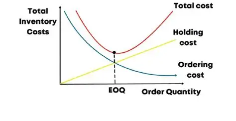
Fixed costs dominate small-batch PCB assembly, including stencil alignment, feeder loading, and pick-and-place programming, which recur each run. As batch size grows, these expenses dilute per board, slashing overall costs in a classic economies-of-scale effect. Variable costs, such as materials and labor, scale linearly but benefit from bulk efficiencies in handling and testing. PCB assembly cost analysis reveals a U-shaped curve: too small inflates setup overhead, too large incurs holding costs and potential rework. Economic order quantity models help pinpoint the sweet spot, factoring demand forecasts against setup and inventory expenses.
Production efficiency improves with moderate batches that align with machine cycle times, reducing downtime between runs. Engineers often model this using basic formulas, adjusting for real-world variables like yield rates. Overlooking these can lead to budget overruns, especially in high-mix, low-volume scenarios common in prototyping.
- Setup Costs: Small batches — High per unit; Medium batches — Balanced; Large batches — Low per unit.
- Material Waste: Small batches — Minimal; Medium batches — Moderate; Large batches — Higher due to spoilage.
- Labor Efficiency: Small batches — Frequent interruptions; Medium batches — Optimal flow; Large batches — Fatigue and error risks.
- Inventory Risk: Small batches — Low; Medium batches — Manageable; Large batches — High obsolescence.
This list illustrates key trade-offs for quick reference during planning.
Quality Dynamics: Navigating Quality vs Quantity
Larger batches amplify quality risks, as process drifts — like inconsistent reflow profiles or stencil wear — propagate across hundreds of boards before detection. Quality vs quantity tension peaks here: high volumes strain inspection resources, potentially missing defects per IPC-A-610 guidelines on solder joint acceptability. Smaller batches enable rapid feedback loops, allowing tweaks for consistent wetting and voiding. However, frequent setups introduce variability from human handling or paste viscosity changes, demanding rigorous process controls.
Thermal management exemplifies this: overcrowded reflow ovens in big batches alter heat transfer, risking component tombstoning or delamination. Optimizing batch size mitigates these by matching load to oven zone capacities, preserving board integrity. Production efficiency suffers if quality slips, as rework cascades into delays. Engineers troubleshoot by monitoring first-pass yields, correlating them to batch volumes.
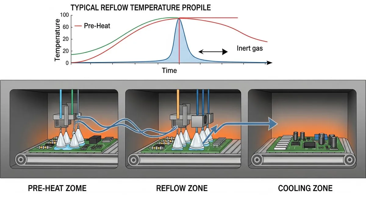
Adhering to J-STD-001 requirements for soldered assemblies ensures baseline quality, regardless of scale. Non-adjacent runs spaced by maintenance further safeguard outcomes.
Factors Influencing Optimal Batch Size
Board design complexity, component lead times, and demand variability dictate ideal sizing. High-density fine-pitch assemblies favor smaller batches to avoid feeder jams or alignment drifts. Conversely, simple through-hole mixes tolerate larger runs for cost savings. Optimizing batch size involves line balancing: matching placer speeds to printer throughput prevents backups. Economic order quantity calculations integrate these, using setup time estimates and holding cost proxies.
Environmental controls play a role too — humidity fluctuations affect paste in prolonged setups, underscoring the need for climate-stable runs. Engineers apply statistical process control to track sigma levels across sizes, refining predictions. Production efficiency peaks when batches sync with downstream test fixtures, minimizing queue times.
Supply chain reliability influences decisions: volatile lead times push toward buffer batches, balancing risk.
Best Practices for Optimizing Batch Size
Start with historical data analysis to baseline setup times and yields per batch tier. Simulate scenarios using production software to forecast PCB assembly cost analysis outcomes. Group similar boards into families, reducing changeover frequency for production efficiency gains. Implement quick-change tooling for feeders and stencils, enabling flexible sizing without full stops.
Quality vs quantity resolves through in-line AOI and SPI at key intervals, catching drifts early. Train operators on batch-specific protocols, like paste agitation intervals. Regularly audit against ISO 9001 quality management principles to sustain improvements. Pilot mixed batches to validate economic order quantity assumptions in your context.
For troubleshooting, if yields drop in large runs, segment into sub-batches with interim checks. Document lessons to iterate, ensuring scalability.
Collaborate across design, procurement, and assembly for holistic optimization.
Real-World Insights from Assembly Challenges
Consider a scenario where a mid-volume run exposed reflow inconsistencies due to uneven oven loading — splitting into smaller batches restored profiles, cutting scrap by aligning with equipment specs. In another, overambitious large batches led to handling dents; introducing edge supports and batch caps resolved it. These highlight optimizing batch size as iterative, rooted in root-cause analysis.
Engineers facing high-mix demands benefit from kanban-style pulling, matching batches to orders dynamically. Such adaptations boost production efficiency without capital outlay.
Conclusion
Batch size profoundly shapes PCB assembly outcomes, demanding careful PCB assembly cost analysis to harness economies while upholding quality. Optimizing batch size through economic order quantity principles and quality vs quantity awareness drives production efficiency. Practical steps like simulation, controls, and standards adherence yield reliable results. Engineers who master these trade-offs deliver robust assemblies on time and budget. Prioritize data-driven decisions for sustained gains.
FAQs
Q1: What role does economic order quantity play in optimizing batch size for PCB assembly?
A1: Economic order quantity balances setup costs against holding expenses, identifying the batch size minimizing total PCB assembly costs. For electric engineers, apply it by estimating demand, setup durations, and inventory factors. This model guides production efficiency, preventing overproduction or frequent small runs. Integrate with yield data for accuracy, ensuring quality vs quantity equilibrium.
Q2: How does batch size impact production efficiency in PCB assembly lines?
A2: Batch size affects production efficiency by influencing setup frequency and throughput matching. Smaller batches enable quick adjustments but increase changeovers, while larger ones risk bottlenecks from process drifts. Optimizing batch size aligns with line capacity, reducing idle time. Monitor cycle times and OEE metrics to refine, supporting consistent output.
Q3: What are key considerations in PCB assembly cost analysis for different batch sizes?
A3: PCB assembly cost analysis weighs fixed setups against variable scaling. Small batches elevate per-unit costs from programming and cleaning; large ones add rework risks. Factor board complexity and material stability. Use curves to visualize, aiding economic order quantity decisions for cost-quality balance.
Q4: How can engineers balance quality vs quantity when selecting batch sizes?
A4: Balancing quality vs quantity involves in-line monitoring and standards like IPC-A-610. Smaller batches allow real-time corrections, curbing defect propagation. Larger ones demand robust SPC to detect drifts early. Optimize via pilots, ensuring production efficiency without yield compromises.
References
IPC-A-610H — Acceptability of Electronic Assemblies. IPC, 2020
J-STD-001H — Requirements for Soldered Electrical and Electronic Assemblies. IPC, 2020
ISO 9001:2015 — Quality Management Systems. ISO, 2015





