ALLPCB


Introduction
In electronics manufacturing, printed circuit boards form the backbone of virtually every device, from consumer gadgets to aerospace systems. Solder joints serve as the vital electrical and mechanical connections between components and the PCB substrate, directly influencing overall PCB reliability solder joints. Despite advances in materials and processes, these joints remain one of the most common points of failure, potentially leading to intermittent connectivity, complete circuit breakdowns, or catastrophic system failures. The importance of solder joint inspection cannot be overstated, as it acts as the primary safeguard in PCB quality control, catching defects before they propagate into field issues. Factory-driven insights reveal that rigorous inspection protocols align production with proven standards, ensuring assemblies meet demanding operational environments. By prioritizing this step, manufacturers mitigate risks associated with solder joint failure causes and elevate product longevity.
Understanding Solder Joints and Their Role in PCB Reliability
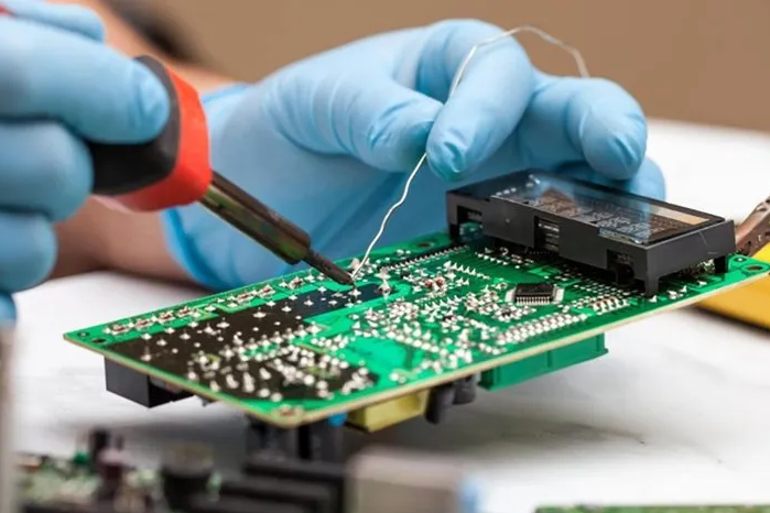
Solder joints form during the reflow soldering process, where molten solder wets the component leads, pads, and traces, solidifying into a metallurgical bond upon cooling. This bond must withstand electrical current, thermal expansion differences, and mechanical stresses throughout the product's lifecycle. In high-density assemblies, thousands of these joints exist per board, making their collective integrity crucial for PCB reliability solder joints. Poorly formed joints compromise signal integrity, power delivery, and structural stability, often manifesting as early-life failures or gradual degradation. Engineers recognize that solder joint quality directly correlates with assembly yield and end-user satisfaction in electronics manufacturing. Factory practices emphasize evaluating joint fillet shape, wetting coverage, and intermetallic compound formation to predict performance.
Common Solder Joint Failure Causes in Electronics Manufacturing
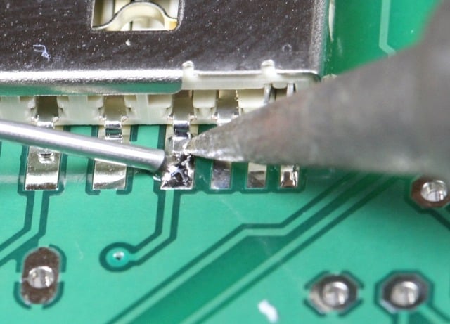
Thermo-mechanical fatigue tops the list of solder joint failure causes, arising from repeated thermal cycling that induces shear stresses due to coefficient of thermal expansion mismatches between components and the PCB. Mechanical vibrations or shocks exacerbate this, cracking the brittle intermetallic layers at the joint interface. Process-related defects, such as insufficient solder volume or bridging between adjacent pads, stem from imprecise stencil printing or reflow profiling. Contamination from flux residues, oxidized surfaces, or particulate matter hinders proper wetting, leading to weak bonds or voids that trap gases during solidification. Overheating during soldering can cause de-wetting or tombstoning, where components lift due to uneven heating. These issues underscore the need for proactive PCB quality control to address root causes at the source.
The Mechanisms Behind Solder Joint Degradation
At the microstructural level, solder joints degrade through creep, where sustained loads at elevated temperatures cause atomic diffusion and grain boundary sliding. Fatigue cracks initiate at stress concentration points, such as joint heels or toes in gull-wing leads, propagating under cyclic loading. Voids, often from solder paste outgassing or flux entrapment, reduce effective cross-sectional area, accelerating current-induced heating and electromigration. In lead-free solders, tin whisker growth poses additional risks, bridging joints and causing shorts. Environmental factors like humidity promote corrosion, undermining joint adhesion over time. Understanding these mechanisms guides engineers in selecting materials and processes resilient to specific application demands.
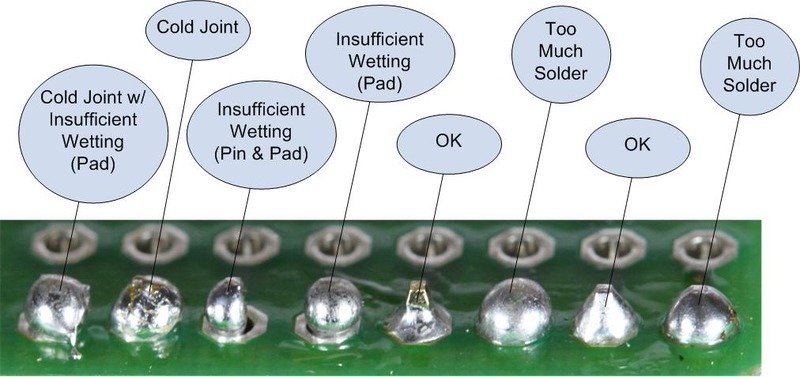
Why Solder Joint Inspection is Essential for PCB Quality Control
Solder joint inspection verifies compliance with defined acceptability criteria, distinguishing good joints from those prone to premature failure. Visual inspection detects surface anomalies like cold joints or excessive solder, while advanced methods reveal subsurface issues invisible to the eye. In high-volume electronics manufacturing, skipping this step risks shipping defective boards, incurring rework costs and warranty claims. The importance of solder joint inspection lies in its ability to provide immediate feedback, enabling process adjustments before batches proceed. Factory insights show that consistent inspection boosts first-pass yields and aligns with industry benchmarks for reliability. IPC-A-610J outlines precise criteria for joint appearance, hole fill, and minimum fillet heights across assembly classes.
Inspection Techniques for Comprehensive Coverage
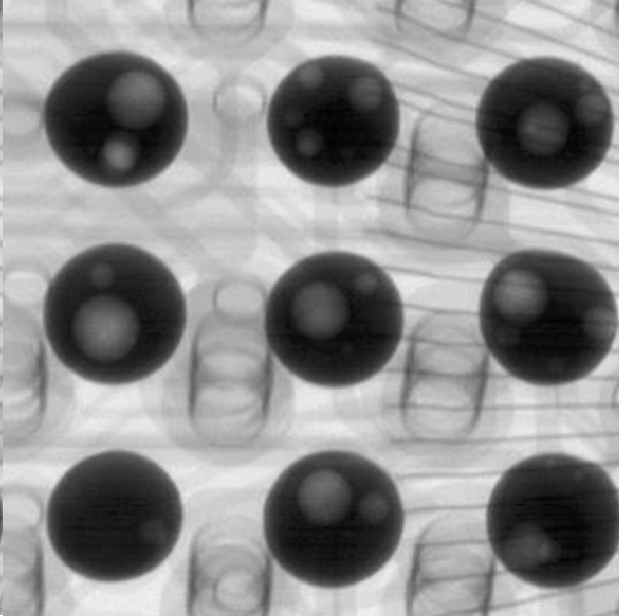
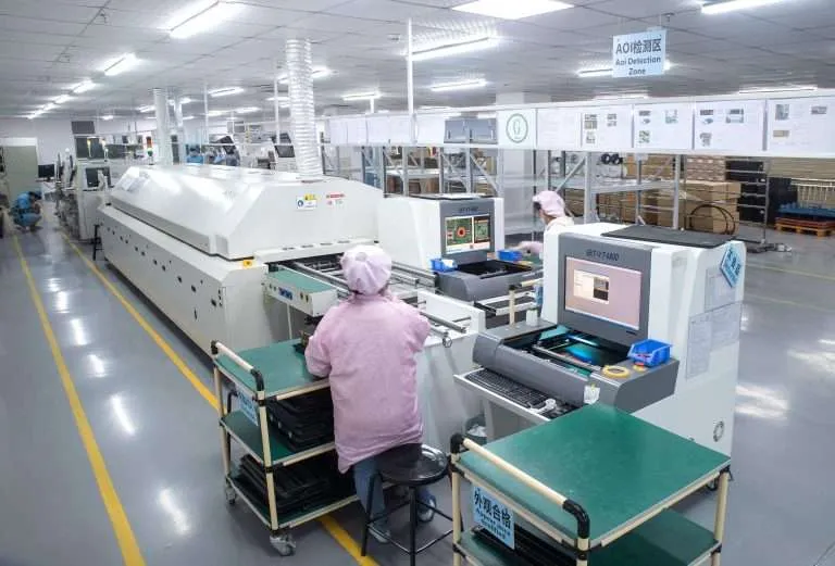
Automated optical inspection systems scan for misalignment, bridging, and insufficient solder using high-resolution cameras and pattern recognition algorithms. X-ray inspection excels for bottom-terminated components like BGAs, detecting voids, head-in-pillow defects, and non-wet opens. Cross-sectioning and metallographic analysis offer definitive verification for failure analysis, though destructive by nature. Endoscopic tools aid in inspecting hard-to-reach areas under large components. Combining these techniques ensures thorough coverage, from pre-reflow paste inspection to post-assembly validation. Each method complements the others, forming a layered defense in PCB quality control.
Best Practices in Solder Joint Inspection Protocols
Implement in-line inspection immediately post-reflow to catch defects early, minimizing downstream rework. Train operators to IPC-A-610J class-specific criteria, fostering consistency across shifts. Maintain controlled environments to prevent handling-induced damage during inspection. Integrate data analytics to track defect trends, correlating them with process parameters like peak reflow temperature or conveyor speed. J-STD-001J provides requirements for soldering processes, including cleanliness and handling to support reliable joints. Document all findings for traceability, enabling continuous improvement in electronics manufacturing.
Advanced Reliability Testing for Solder Joints
Accelerated life testing simulates years of service through thermal cycling, vibration, and humidity exposure, quantifying joint endurance. Standards like IPC-9701 define test conditions and failure criteria, such as resistance increases or cycles to open circuit. These protocols help validate designs before full-scale production. Finite element modeling predicts stress hotspots, informing layout optimizations. Field data feedback loops refine models, closing the gap between lab results and real-world performance. Such factory-driven approaches ensure PCB reliability solder joints under diverse conditions.
Case Insights: Troubleshooting Persistent Solder Issues
In one manufacturing scenario, recurring voiding traced back to solder paste storage exceeding recommended humidity levels, resolved by environmental controls and paste age tracking. Another case involved heel cracking in QFP leads, mitigated by adjusting reflow profiles to reduce peak temperatures and dwell times. Bridging incidents often linked to stencil wear, prompting regular maintenance schedules. These examples highlight how inspection data drives root cause analysis, preventing recurrence. Engineers benefit from systematic troubleshooting, turning failures into process enhancements.
Conclusion
Solder joint inspection stands as a cornerstone of PCB quality control, directly safeguarding electronics manufacturing against common failure modes. By addressing solder joint failure causes through rigorous protocols and standard compliance, manufacturers achieve superior PCB reliability solder joints. The importance of solder joint inspection extends beyond immediate defect detection to long-term product assurance. Adopting factory-driven best practices, including IPC-guided criteria, empowers teams to deliver robust assemblies. Prioritizing this non-negotiable step minimizes risks, optimizes yields, and supports innovation in demanding applications.
FAQs
Q1: What are the primary solder joint failure causes in PCB assemblies?
A1: Common solder joint failure causes include thermo-mechanical fatigue from thermal cycling, mechanical stresses like vibration, and process defects such as voids or poor wetting due to contamination. Flux residues or improper reflow profiles exacerbate these issues, weakening the intermetallic bond. Addressing them through PCB quality control prevents early failures and ensures reliability in electronics manufacturing.
Q2: Why is the importance of solder joint inspection emphasized in electronics manufacturing?
A2: The importance of solder joint inspection lies in detecting defects like bridges, insufficient solder, or hidden voids that compromise PCB reliability solder joints. It provides process feedback, reduces rework, and verifies compliance with standards, preventing field failures. Factory protocols integrate it to maintain high yields and product integrity across production runs.
Q3: How does IPC-A-610J contribute to PCB quality control for solder joints?
A3: IPC-A-610J defines acceptability criteria for solder joints, specifying fillet dimensions, wetting requirements, and defect classifications by assembly class. It guides visual and automated inspections, ensuring consistent quality in electronics manufacturing. Manufacturers use it to standardize evaluations, enhancing PCB reliability solder joints and minimizing variability.
Q4: What best practices improve outcomes from solder joint inspection?
A4: Best practices include in-line post-reflow checks, operator training per J-STD-001J, and combining AOI with X-ray for full coverage. Track defect data to refine processes like stencil alignment and reflow settings. This approach bolsters PCB quality control and addresses solder joint failure causes proactively.
References
IPC-A-610J — Acceptability of Electronic Assemblies. IPC, 2024
IPC J-STD-001J — Requirements for Soldered Electrical and Electronic Assemblies. IPC, 2024
IPC-9701 — Performance Test Specification and Qualification Requirements for Surface Mount Solder Attachments. IPC, 2011