 ALLPCB


Laser cutting has become a preferred method for producing unmounted stencils used in surface mount technology processes. Engineers rely on this technique to create precise apertures that deposit solder paste accurately onto printed circuit boards. The approach supports high-volume production while maintaining tight tolerances required for modern component packages. Unmounted stencils offer flexibility during assembly because they can be tensioned in reusable frames or used in dedicated fixtures. This flexibility reduces storage needs and allows quick changes between different board designs.
Why Laser Cutting Matters for Unmounted Stencils
Unmounted stencils produced through laser cutting deliver consistent performance in demanding manufacturing environments. The process removes material with a focused beam that creates clean edges without mechanical stress on the sheet. Engineers value this method because it supports fine feature sizes needed for small passive components and high-density interconnects. When stencil cutting precision is prioritized, the resulting apertures maintain uniform wall angles and smooth surfaces that improve paste release. Practical experience shows that well-executed laser cut stencil service reduces defects such as bridging and insufficient solder during reflow.
Technical Principles of Laser Cutting
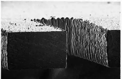
The laser cutting process for unmounted stencils begins with a computer-controlled beam that follows a programmed path based on the stencil design file. Material removal occurs through localized melting and vaporization, which produces apertures with minimal burrs when parameters are optimized. Engineers adjust beam power, pulse frequency, and travel speed to match the thickness and type of sheet being processed. This control directly influences aperture accuracy laser cutting results, especially for trapezoidal or stepped profiles that aid paste release. Consistent beam alignment and focus throughout the cut prevent variations that could affect paste volume on the board.
Related Reading: Laser Cut vs. Etched Stencils: A Comprehensive Material Comparison for SMT
Achieving Aperture Accuracy in Laser Cutting
Aperture accuracy laser cutting depends on several controllable factors during the manufacturing sequence. Proper fixturing of the unmounted sheet prevents movement that could shift the cut location by even a few micrometers. Engineers verify beam calibration regularly to ensure the laser maintains the intended spot size and energy density across the entire stencil area. Post-cut inspection using optical measurement tools confirms that aperture dimensions stay within specified tolerances before the stencil leaves the production floor. These steps collectively support reliable solder paste deposition volumes required for fine-pitch components.
Selecting Suitable Laser Cutting Materials
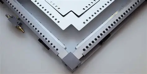
Laser cutting materials for unmounted stencils are chosen primarily for their mechanical stability and compatibility with the laser process. Stainless steel sheets remain the most common choice because they resist deformation under tension and provide good thermal conductivity during cutting. Thickness selection typically ranges from 0.1 mm to 0.2 mm depending on the required paste volume and component pitch. Engineers evaluate material flatness and surface finish prior to cutting to avoid introducing variations in aperture quality. Proper material handling after cutting preserves the precision achieved during the laser process.
Understanding Laser Cutting Cost Factors
Laser cutting cost is influenced by several variables that engineers evaluate when planning stencil production. Sheet thickness and overall stencil size affect processing time and therefore total expense. Design complexity, such as the number of apertures or the presence of stepped features, increases programming and cutting duration. Material grade and any required post-processing steps like electropolishing also contribute to the final price. Procurement teams often compare multiple laser cut stencil service providers to balance precision requirements against budget constraints for prototype versus production volumes.
Best Practices for Optimal Results
Engineers achieve the best outcomes by providing clean Gerber or CAD data files that include accurate aperture definitions and fiducial locations. Maintaining consistent laser parameters across similar jobs reduces variability between successive stencils. Regular verification of machine calibration and beam alignment supports long-term stencil cutting precision. When troubleshooting paste release issues, teams often examine aperture wall quality first before adjusting other process variables. These practical steps help maintain high first-pass yields during assembly.
Related Reading: Precision Solder Paste Application: Mastering Laser Cut Stencils for Fine-Pitch PCBs
Troubleshooting Common Issues
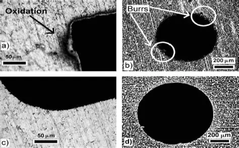
When aperture accuracy falls short, engineers first check the laser focus and power settings used during cutting. Uneven material thickness or residual stress in the sheet can also cause dimensional drift that appears only after the stencil is tensioned. In such cases, switching to a different batch of laser cutting materials or adding a stress-relief step before cutting often resolves the problem. Paste volume inconsistencies frequently trace back to burrs or rough walls, which can be addressed through optimized cutting parameters or light post-processing. Systematic root-cause analysis prevents repeated defects across multiple production runs.
Conclusion
Laser cutting remains an effective method for producing unmounted stencils that meet the precision demands of contemporary electronics assembly. Attention to beam parameters, material selection, and post-cut verification directly supports aperture accuracy and overall process reliability. Engineers who apply these principles consistently experience fewer printing defects and improved throughput. As component sizes continue to shrink, maintaining strict control over every aspect of the laser cutting process becomes increasingly important for achieving repeatable results.
FAQs
Q1: How does laser cut stencil service improve aperture accuracy compared with other methods?
A1: Laser cut stencil service creates apertures through a non-contact process that avoids tool wear and mechanical distortion. This results in smoother walls and more consistent dimensions across the entire stencil area. Engineers often select this service when fine-pitch components require tight control over paste volume. Proper parameter selection during cutting further enhances the final accuracy.
Q2: What factors affect stencil cutting precision during laser processing?
A2: Stencil cutting precision depends on beam focus, travel speed, pulse settings, and sheet fixturing. Any variation in these parameters can shift aperture location or alter wall angles. Engineers monitor these variables closely and perform regular machine calibration to maintain consistent results. Material flatness also plays a significant role in achieving the required precision.
Q3: Which laser cutting materials are best suited for high-accuracy unmounted stencils?
A3: Stainless steel sheets with controlled thickness and high surface quality are widely used for high-accuracy unmounted stencils. These materials maintain dimensional stability when tensioned and respond well to laser processing. Engineers evaluate flatness and thickness tolerance before selecting a material lot for critical jobs. Proper storage prevents surface contamination that could affect cut quality.
Q4: How is laser cutting cost determined for unmounted stencil production?
A4: Laser cutting cost reflects material thickness, stencil size, design complexity, and any additional finishing steps. More apertures or stepped features increase programming and cutting time, raising the overall expense. Engineers balance these factors against required precision levels when requesting quotes. Volume orders typically reduce the per-unit cost for production runs.
References
IPC-7525B — Stencil Design Guidelines. IPC, 2012
IPC-A-610G — Acceptability of Electronic Assemblies. IPC, 2017
ISO 9001:2015 — Quality Management Systems. ISO, 2015


