 ALLPCB


In the fast-evolving world of electronics, video processing printed circuit boards (PCBs) are at the heart of devices like cameras, gaming consoles, and streaming hardware. These PCBs handle high-speed data and intensive workloads, which generate significant heat. Without proper thermal management, this heat can degrade performance, shorten component lifespan, and cause system failures. So, how can you ensure effective heat dissipation in video processing PCBs? This guide dives deep into proven thermal management strategies, from design tips to cooling solutions, tailored specifically for video PCB thermal design.
Whether you're an engineer designing high-performance video systems or a manufacturer seeking reliable solutions, this comprehensive resource will explore PCB heat dissipation for video processing, thermal simulation for video PCBs, cooling solutions for video PCBs, and the role of thermal vias in video processing PCB designs. Let's get started with actionable insights to keep your designs cool and efficient.
Why Thermal Management Matters for Video Processing PCBs
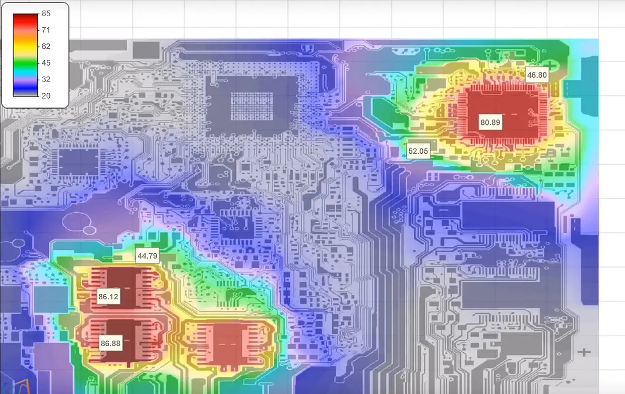
Video processing PCBs are unique due to their high power density and continuous operation. Components like GPUs, FPGAs, and high-speed processors used in these boards often operate at peak capacity, generating heat that can exceed 100°C if not managed properly. Excessive heat can lead to thermal throttling, where components slow down to prevent damage, or even permanent failure of critical parts. Effective thermal management ensures reliability, maintains performance, and extends the lifespan of the device.
Beyond performance, poor heat dissipation can cause signal integrity issues in video processing systems. High temperatures may alter the electrical properties of traces and components, leading to data errors or dropped frames. With the demand for 4K and 8K video processing growing, thermal challenges are only becoming more critical. Let’s explore the key strategies for tackling these issues in video PCB thermal design.
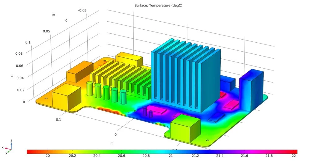
Key Challenges in PCB Heat Dissipation for Video Processing
Before diving into solutions, it's important to understand the specific thermal challenges faced by video processing PCBs:
- High Power Components: Processors and graphic chips on these boards often consume 20-50 watts or more, creating concentrated heat sources.
- Compact Designs: Modern video devices demand smaller form factors, limiting space for cooling solutions and increasing thermal density.
- Continuous Operation: Unlike some electronics, video processing systems often run for hours, leading to sustained heat buildup.
- Signal Speed: High-frequency signals (often exceeding 5 GHz for video data) are sensitive to temperature-induced impedance changes, affecting performance.
Addressing these challenges requires a multi-layered approach to PCB heat dissipation for video processing. Let’s look at the most effective strategies.
Thermal Management Strategies for Video Processing PCBs
1. Optimize PCB Layout for Heat Distribution
The foundation of effective thermal management starts with the PCB layout. A well-designed layout can significantly reduce hotspots and improve heat dissipation. Here are some tips for video PCB thermal design:
- Component Placement: Place high-power components like processors and memory chips away from each other to avoid concentrated heat zones. Ensure they are near areas with good airflow or heat sinks.
- Ground Planes: Use large copper ground planes to act as heat spreaders. Copper has a thermal conductivity of about 400 W/m·K, making it an excellent medium for distributing heat across the board.
- Trace Widths: Widen power traces to reduce resistive heating. For high-current paths (e.g., 5A or more), calculate trace width using tools based on IPC-2221 standards to minimize heat generation.
2. Leverage Thermal Vias in Video Processing PCB Designs
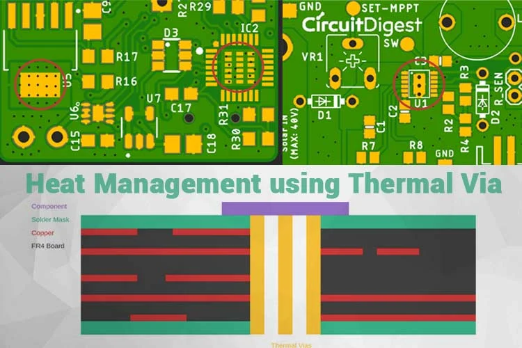
Thermal vias are small holes filled or plated with copper that transfer heat from one layer of the PCB to another, often connecting to a heat sink or ground plane. For video processing PCBs, thermal vias are critical due to the high heat output of components. Here's how to use them effectively:
- Placement: Position thermal vias directly under or near high-power components to create a direct path for heat to escape. A grid of 0.3 mm vias spaced 1.2 mm apart can reduce component temperature by up to 20%.
- Quantity: Use multiple vias to increase thermal conductivity. Studies suggest that 8-12 vias per square centimeter under a hot component can significantly lower junction temperatures.
- Connection: Connect vias to internal copper layers or external heat sinks to maximize heat transfer away from sensitive areas.
Thermal vias in video processing PCB designs are a cost-effective way to manage heat without adding bulky external cooling systems. However, overusing vias can compromise structural integrity, so balance is key.
3. Choose the Right Materials for Thermal Performance
The materials used in PCB construction play a huge role in thermal management. Standard FR-4 material has a thermal conductivity of only 0.25 W/m·K, which is insufficient for high-power video processing boards. Consider these alternatives:
- High-Tg FR-4: With a glass transition temperature above 170°C, high-Tg FR-4 withstands higher operating temperatures without deforming.
- Metal-Core PCBs (MCPCBs): These use a metal base (often aluminum) with thermal conductivity up to 200 W/m·K, ideal for dissipating heat in compact video devices.
- Thick Copper Layers: Opt for 2 oz or 3 oz copper (70-105 μm thickness) instead of the standard 1 oz to enhance heat spreading and reduce resistive losses.
Selecting materials tailored for PCB heat dissipation in video processing can prevent thermal issues before they start, especially in high-performance applications.
4. Implement Active and Passive Cooling Solutions for Video PCBs
Cooling solutions for video PCBs fall into two categories: passive and active. Both have their place depending on the design requirements and heat load.
Passive Cooling:
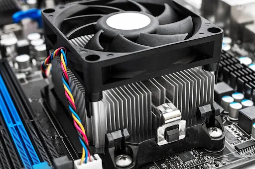
- Heat Sinks: Attach heat sinks to high-power components to increase surface area for heat dissipation. A well-designed heat sink can reduce component temperatures by 10-30°C.
- Thermal Pads and Compounds: Use thermal interface materials (TIMs) with conductivity of 1-5 W/m·K to improve heat transfer between components and heat sinks.
Active Cooling:
- Fans: Small, low-noise fans can be integrated into video processing devices to force air over hot components, reducing temperatures by up to 40% in confined spaces.
- Liquid Cooling: For extreme cases, liquid cooling systems can be used to manage heat in high-end video processing hardware, though they add complexity and cost.
Choosing the right cooling solutions for video PCBs depends on factors like power consumption, enclosure size, and noise constraints. For most designs, a combination of passive and active methods works best.
5. Use Thermal Simulation for Video PCB Design Validation
Designing for thermal performance is only half the battle—validating the design is equally important. Thermal simulation for video PCBs allows engineers to predict heat distribution, identify hotspots, and test cooling solutions before manufacturing. Here’s how simulation helps:
- Hotspot Detection: Simulation software can model heat flow and pinpoint areas where temperatures exceed safe limits (e.g., above 85°C for most ICs).
- Material Testing: Test different board materials and layouts virtually to see how they impact thermal performance without building physical prototypes.
- Cooling Optimization: Simulate airflow and heat sink efficiency to fine-tune cooling solutions, saving time and cost in the design phase.
Thermal simulation for video PCBs typically involves tools that use finite element analysis (FEA) to model heat transfer. By running simulations under worst-case scenarios (e.g., maximum load at 40°C ambient temperature), designers can ensure reliability in real-world conditions.
Best Practices for Long-Term Thermal Reliability
Beyond specific strategies, adopting best practices ensures long-term thermal reliability for video processing PCBs:
- Derating Components: Operate components below their maximum rated power and temperature (e.g., at 80% capacity) to reduce heat stress and extend lifespan.
- Environmental Consideration: Design for the operating environment. If the device will be used in high ambient temperatures (above 35°C), prioritize robust cooling solutions.
- Regular Testing: Use thermal imaging cameras during testing to monitor real-world heat dissipation and validate simulation results.
Conclusion: Building Cooler, More Reliable Video Processing PCBs
Thermal management is a critical aspect of designing video processing PCBs. From optimizing layouts and using thermal vias in video processing PCB designs to selecting high-performance materials and leveraging cooling solutions for video PCBs, every step counts in preventing heat-related issues. Additionally, thermal simulation for video PCBs ensures that designs are validated before production, saving time and resources.
By applying these strategies for PCB heat dissipation in video processing, engineers can create systems that deliver high performance without overheating. Whether you're working on a compact streaming device or a powerful video editing workstation, effective video PCB thermal design is the key to reliability and efficiency. Start implementing these techniques in your next project to keep your designs cool under pressure.
At ALLPCB, we’re committed to supporting your thermal management needs with high-quality materials, precise manufacturing, and expert guidance. Let’s build the future of video processing technology together, one cool PCB at a time.





