ALLPCB


If you're looking to design a printed circuit board (PCB) for a pet tracking device, you've come to the right place. This comprehensive guide will walk you through every step of creating a pet tracking PCB, from initial concept to a functional device ready for your pet's collar. We'll cover key aspects like layout, components, antenna design, power optimization, and enclosure considerations to ensure your design is efficient, reliable, and compact.
Whether you're an engineer or a hobbyist, this guide provides actionable tips and detailed insights to help you build a high-performing pet tracking system. Let's dive into the essentials of pet tracking PCB design and explore how to bring your idea to life.
Why Pet Tracking PCB Design Matters
Pet tracking devices have become essential tools for pet owners who want to keep tabs on their furry friends. These devices rely on a well-designed PCB to integrate GPS, communication modules, and power systems into a small, wearable form factor. A poorly designed PCB can lead to signal loss, high power consumption, or even device failure, which could mean losing track of your pet. By focusing on a solid pet tracking PCB layout, carefully selected components, and optimized design, you ensure reliability and performance.
In the sections below, we'll break down each critical element of pet tracking PCB design to help you create a device that's both effective and durable.
Step 1: Planning Your Pet Tracking PCB Layout
The foundation of any successful pet tracking device starts with a well-thought-out PCB layout. The pet tracking PCB layout determines how components are placed and connected, impacting signal integrity, power efficiency, and overall size. Since pet trackers need to be small and lightweight for collar attachment, space optimization is key.
Begin by defining the core functionalities of your device. Most pet trackers include GPS for location tracking, a wireless communication module (like cellular or Bluetooth), a microcontroller for processing data, and a power source. Map out these components on your PCB design software, ensuring minimal interference between high-frequency signals (like GPS) and other circuitry.
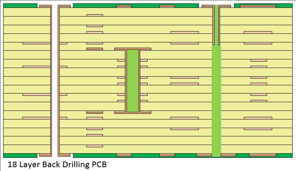
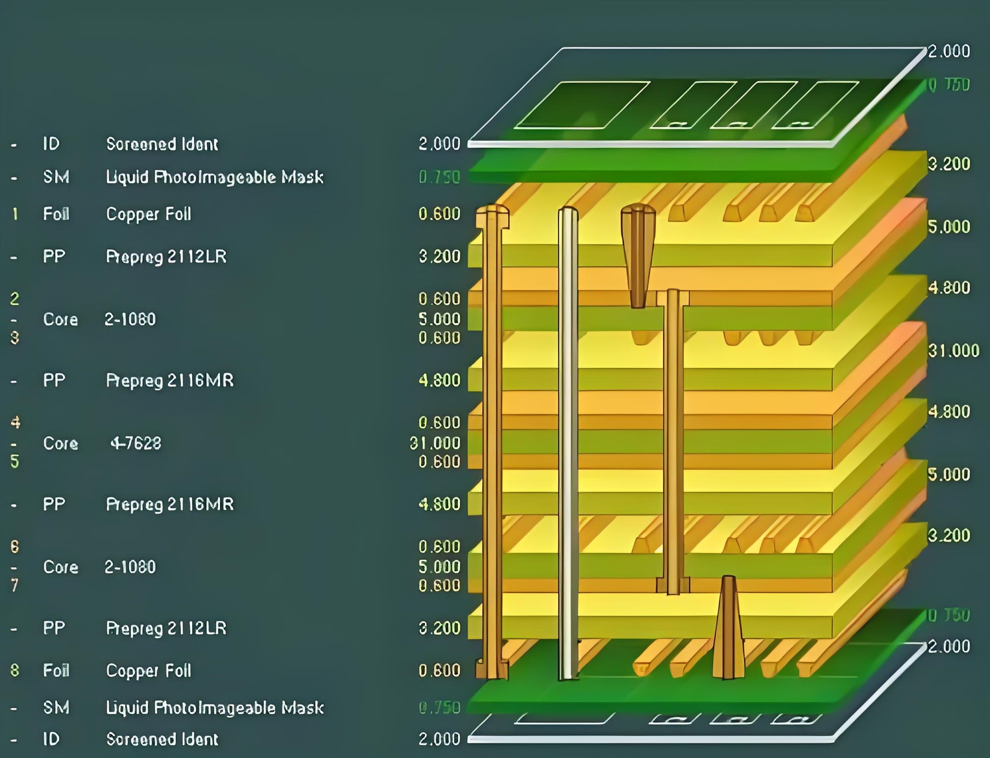
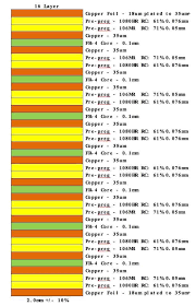
Keep high-speed signal traces short and direct to reduce noise. For instance, GPS signals operate at frequencies around 1.575 GHz, so traces should be as short as possible to avoid signal degradation. Place sensitive components like the GPS module away from noisy elements such as power regulators. Also, consider using a multi-layer PCB design—typically 4 layers—to separate power, ground, and signal planes for better noise isolation.

Step 2: Selecting the Right Pet Tracking PCB Components
Choosing the right pet tracking PCB components is critical for functionality and compactness. Here’s a breakdown of the essential components you’ll need and tips for selecting them:
- GPS Module: Opt for a compact GPS module with low power consumption. Look for modules with a sensitivity of at least -160 dBm to ensure accurate location tracking even in weak signal areas.
- Microcontroller (MCU): Select a low-power MCU with enough processing capability to handle GPS data and communication protocols. A 32-bit MCU with a clock speed of 48 MHz or higher is often sufficient for pet trackers.
- Communication Module: Depending on your range requirements, choose between cellular (for long-range tracking) or Bluetooth (for short-range). Cellular modules supporting 4G LTE Cat-M1 are ideal for wide coverage with low power usage.
- Battery and Power Management: Use a small rechargeable lithium-ion battery (around 3.7V, 500mAh) paired with a power management IC to regulate voltage and extend battery life.
- Sensors: Some trackers include accelerometers to detect pet movement, helping to save power by entering sleep mode when the pet is stationary.
When sourcing components, prioritize those with small footprints like QFN or BGA packages to save space on the PCB. Always check datasheets for power requirements and thermal characteristics to avoid overheating in a confined collar device.
Step 3: Mastering Pet Tracking PCB Antenna Design
The antenna is the heart of wireless communication in a pet tracking device, making pet tracking PCB antenna design a crucial step. A poorly designed antenna can result in weak signals, reducing the tracker’s range and reliability. Since pet trackers often use GPS and cellular or Bluetooth signals, you may need multiple antennas or a multi-band antenna.
For GPS, a ceramic patch antenna is a popular choice due to its compact size and high gain (typically 2-5 dBi). Place the antenna on the top layer of the PCB with a clear ground plane beneath it to improve signal reception. Ensure a keep-out area around the antenna—usually specified in the datasheet (e.g., 5mm clearance)—to avoid interference from other components.
For cellular or Bluetooth communication, consider a PCB trace antenna or a chip antenna. Trace antennas are cost-effective and can be designed directly on the PCB, but they require precise impedance matching to 50 ohms to maximize efficiency. Use a network analyzer during testing to fine-tune the antenna’s performance.
Antenna placement is also critical. Position it away from metal parts of the collar or enclosure, as metal can detune the antenna and degrade performance. If space is limited, consider integrating the antenna into the PCB layout, but be prepared to iterate on the design for optimal results.

Step 4: Focusing on Pet Tracking PCB Power Optimization
Power efficiency is a top priority in pet tracking devices since they often run on small batteries and need to last for days or weeks. Effective pet tracking PCB power optimization can make the difference between a device that needs frequent charging and one that offers long-term reliability.
Start by selecting low-power components wherever possible. For instance, choose a GPS module that supports duty-cycling, where it only activates periodically to update location data. Similarly, use an MCU with deep sleep modes that consume less than 10 μA when idle.
Design your power management circuit to minimize losses. Use a buck-boost converter if the battery voltage varies significantly during discharge, ensuring a stable output voltage (e.g., 3.3V) for the components. Add bypass capacitors near power pins of ICs to reduce noise—typically 0.1 μF ceramic capacitors work well for high-frequency filtering.
Software also plays a role in power optimization. Program the device to enter sleep mode when the pet is inactive, using data from an accelerometer to trigger wake-ups only during movement. This can cut power consumption by up to 80% in some scenarios.
Finally, test the power draw of your assembled PCB using a multimeter to identify any unexpected current leaks. A typical pet tracker should aim for an average current draw of less than 5 mA in active mode and under 100 μA in sleep mode.
Step 5: Designing a Pet Tracking PCB Enclosure
The pet tracking PCB enclosure protects the electronics from moisture, dust, and physical impact while ensuring the device remains comfortable for the pet to wear. A well-designed enclosure also contributes to the device’s signal performance and battery accessibility.
Choose a lightweight, durable material like ABS plastic for the enclosure, as it offers good impact resistance and is easy to mold into small shapes. The enclosure should be IP65-rated or higher to provide water and dust resistance, considering that pets may run through rain or mud.
Size is a critical factor. The enclosure must be compact enough to fit on a collar without weighing the pet down—aim for dimensions around 40mm x 30mm x 10mm for small to medium pets. Ensure there’s enough internal space for the PCB, battery, and antenna without crowding, as tight spacing can cause heat buildup.
Pay attention to antenna placement within the enclosure. Avoid covering the antenna area with metal or thick plastic, as this can block signals. If possible, design a small window or use a thinner material over the antenna to maintain signal strength.
Lastly, consider how the enclosure attaches to the collar. A secure clip or loop mechanism works well, and some designs include a slot for easy battery replacement or charging access. Test the enclosure with a prototype to ensure it withstands daily wear and tear from an active pet.

Step 6: Testing and Iterating Your Pet Tracking PCB Design
Once your PCB and enclosure are assembled, thorough testing is essential to validate performance. Start by checking the GPS accuracy—take the device outdoors and compare reported locations with known coordinates. Ensure the error is within 5-10 meters, which is typical for consumer-grade GPS.
Test the communication range for cellular or Bluetooth modules. For cellular trackers, verify connectivity over several kilometers in different environments (urban and rural). For Bluetooth, ensure a stable connection within 10-20 meters, depending on the module’s specifications.
Monitor power consumption over a few days to confirm battery life matches your design goals. If the device drains faster than expected, revisit power optimization strategies or check for circuit inefficiencies.
Finally, conduct real-world tests by attaching the tracker to a pet collar and observing its performance during daily activities. Look for issues like signal loss, overheating, or enclosure durability. Use feedback from these tests to refine your design before final production.
Conclusion: Building a Better Pet Tracker with PCB Design
Designing a pet tracking device from concept to collar involves careful planning and attention to detail in every aspect of PCB development. By focusing on an efficient pet tracking PCB layout, selecting the right components, optimizing antenna design, prioritizing power efficiency, and crafting a durable enclosure, you can create a reliable and user-friendly tracker that keeps pets safe.
At ALLPCB, we’re committed to supporting engineers and innovators in bringing their ideas to life. Whether you’re prototyping a pet tracking device or scaling up for production, our expertise in PCB manufacturing can help streamline your process. Start with the steps outlined in this guide, and you’ll be well on your way to designing a cutting-edge pet tracking solution.