ALLPCB


If you're an electrical engineer wondering whether 3 oz copper PCBs are worth the cost, the answer depends on your project’s specific needs. For high-current, high-power applications, 3 oz copper PCBs can be a game-changer due to their enhanced current-carrying capacity and thermal dissipation. However, for standard designs, the added cost may not justify the benefits compared to the more common 1 oz copper PCBs. In this detailed guide, we’ll break down the 3 oz copper PCB cost analysis, compare 3 oz copper PCB vs 1 oz copper, and explore key factors like PCB material selection, PCB cost drivers, and PCB manufacturing price comparison to help you make an informed decision.
Introduction to Copper Thickness in PCBs
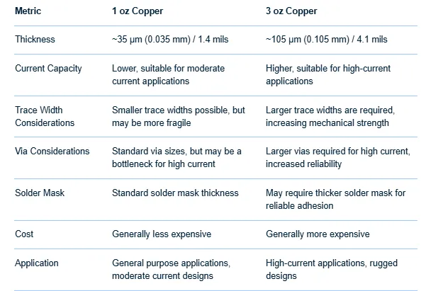
Printed Circuit Boards (PCBs) are the backbone of modern electronics, and copper thickness plays a critical role in their performance. Copper thickness is measured in ounces per square foot (oz/ft2), where 1 oz copper translates to a thickness of about 1.37 mils (35 microns). A 3 oz copper layer is roughly three times thicker, at around 4.13 mils (105 microns). This increased thickness offers unique advantages but also comes with a higher price tag. So, when should you opt for a 3 oz copper PCB, and does the performance justify the cost?
In this blog, we’ll dive deep into the technical and financial aspects of using 3 oz copper PCBs, helping electrical engineers like you weigh the pros and cons for your next project.
What is a 3 oz Copper PCB?
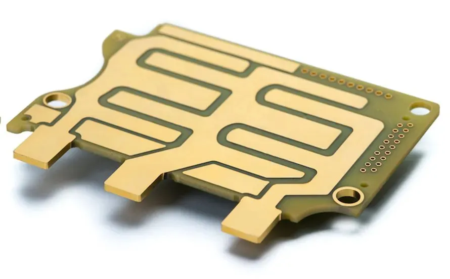
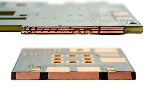
A 3 oz copper PCB refers to a circuit board where the copper foil used for traces and planes weighs 3 ounces per square foot. This heavier copper is often classified as "heavy copper" in the industry, typically used in applications requiring high current or better heat dissipation. After manufacturing processes like plating, the final copper thickness on outer layers might increase to around 4 oz, while inner layers remain closer to 3 oz.
Heavy copper PCBs are common in industries like automotive, power electronics, and industrial equipment, where reliability under high electrical and thermal stress is critical. But with this added durability comes increased manufacturing complexity and cost, which we’ll explore in detail.
3 oz Copper PCB vs 1 oz Copper: Key Differences
Understanding the differences between 3 oz copper PCB vs 1 oz copper is essential for making the right choice for your design. Let’s compare them across key parameters:
- Current-Carrying Capacity: A 3 oz copper layer can handle significantly more current than 1 oz copper. For example, a 10-mil wide trace with 1 oz copper can carry about 1.2 amps at a 10°C temperature rise, while the same trace with 3 oz copper can handle closer to 3.5 amps under similar conditions (based on standard IPC-2221 calculators). This makes 3 oz copper ideal for power supply circuits or motor control applications.
- Thermal Dissipation: Thicker copper acts as a better heat sink, spreading heat more effectively across the board. This is crucial for components like power transistors or LEDs that generate significant heat.
- Mechanical Strength: The added thickness of 3 oz copper provides greater mechanical stability, reducing the risk of trace damage during handling or operation in harsh environments.
- Cost: Manufacturing a 3 oz copper PCB is more expensive due to higher raw material costs and the complexity of etching and plating thicker copper. We’ll dive deeper into this in the cost analysis section.
- Design Constraints: Thicker copper requires wider trace spacing to avoid issues during etching. For instance, while 1 oz copper might allow a 5-mil spacing, 3 oz copper often needs 10 mils or more, potentially limiting how compact your design can be.
Applications of 3 oz Copper PCBs
Before diving into the 3 oz copper PCB cost analysis, let’s look at where these heavy copper boards shine. They are typically used in:
- Power Electronics: Devices like inverters, converters, and power supplies often require high current handling, making 3 oz copper a preferred choice.
- Automotive Systems: Electric vehicle battery management systems and motor controllers benefit from the durability and thermal management of heavy copper.
- Industrial Equipment: High-power machinery and control systems often operate under extreme conditions, where 3 oz copper ensures reliability.
- LED Lighting: High-power LEDs generate significant heat, and thicker copper helps dissipate it, extending the lifespan of the lighting system.
If your project falls into one of these categories, the added cost of 3 oz copper might be worth it. But for low-power or standard electronics, 1 oz copper is often sufficient.
3 oz Copper PCB Cost Analysis: Breaking Down the Numbers
One of the biggest concerns for engineers is whether the benefits of 3 oz copper justify the price. Let’s break down the 3 oz copper PCB cost analysis and explore the main PCB cost drivers.
Raw Material Costs
The primary driver of cost is the copper itself. Since 3 oz copper uses three times the material of 1 oz copper, the base material cost is significantly higher. Copper prices fluctuate, but as a rough estimate, if 1 oz copper costs $0.50 per square foot in a PCB, 3 oz copper could cost around $1.50 per square foot, excluding other manufacturing factors.
Manufacturing Complexity
Etching and plating thicker copper layers require more time and precision. The etching process for 3 oz copper is slower and more challenging, as it’s harder to achieve clean traces and spacing with thicker material. This increases labor and equipment costs. Additionally, plating processes for outer layers add to the final thickness, further raising expenses.
Board Size and Layer Count
Larger boards and those with multiple layers amplify the cost difference. For instance, a 4-layer PCB with 3 oz copper on all layers will be far more expensive than a similar board with 1 oz copper. According to industry insights, moving from 1 oz to 3 oz copper can increase the total board cost by 30-50%, depending on the design complexity and manufacturer.
Volume and Prototyping
For small runs or prototypes, the cost per unit is even higher due to setup fees and lower economies of scale. A single 3 oz copper PCB prototype might cost $100-$200 more than a 1 oz version for a standard 100mm x 100mm board. In high-volume production, the per-unit cost difference narrows but remains significant.
PCB Manufacturing Price Comparison: 1 oz vs 3 oz Copper
When conducting a PCB manufacturing price comparison, it’s clear that 3 oz copper PCBs are more expensive across the board. Here’s a simplified example based on typical industry pricing for a 2-layer, 100mm x 100mm PCB (prices are illustrative and vary by manufacturer and region):
- 1 oz Copper PCB: $50 for a prototype, $0.50 per unit in a 10,000-unit run.
- 3 oz Copper PCB: $80 for a prototype, $0.80 per unit in a 10,000-unit run.
These numbers highlight a consistent 50-60% cost increase for 3 oz copper. However, the price gap can grow or shrink based on additional factors like surface finish, board thickness, and lead time. For instance, opting for an ENIG (Electroless Nickel Immersion Gold) finish or a faster turnaround time will further increase costs for both options, but the proportional increase is often higher for 3 oz due to material handling challenges.
PCB Material Selection: Is 3 oz Copper Right for Your Design?
Choosing the right copper thickness as part of PCB material selection involves balancing performance, reliability, and budget. Here are some questions to guide your decision:
- What are the current and power requirements? Use tools like the IPC-2221 current calculator to determine if 1 oz copper is sufficient or if 3 oz is necessary. If your traces need to carry more than 2-3 amps continuously, 3 oz might be worth considering.
- What are the thermal constraints? If your design includes high-power components, simulate the thermal performance to see if thicker copper significantly reduces hotspot temperatures.
- What is the operating environment? Harsh conditions, such as high vibration or temperature swings in automotive or industrial settings, might justify the added durability of 3 oz copper.
- What is your budget? If cost is a major constraint and performance requirements can be met with wider traces or additional cooling on a 1 oz board, it might not make sense to upgrade to 3 oz.
As an engineer, I’ve worked on projects where 1 oz copper was pushed to its limits in a power supply design. By widening traces and adding thermal vias, we avoided the cost of moving to 3 oz copper without sacrificing reliability. However, in a recent high-current motor controller project, switching to 3 oz copper reduced trace resistance and heat buildup, ultimately saving us from potential field failures. These real-world trade-offs are worth considering in your designs.
Pros and Cons of 3 oz Copper PCBs
Let’s summarize the advantages and disadvantages to help you weigh whether 3 oz copper PCBs are worth the investment.
Pros:
- Higher current-carrying capacity for power-intensive applications.
- Better thermal management, reducing the risk of overheating.
- Increased mechanical strength, ideal for rugged environments.
Cons:
- Significantly higher cost due to materials and manufacturing complexity.
- Design limitations, such as wider trace spacing, which can impact board size.
- Not necessary for low-power or standard applications, making it an overkill in many cases.
Alternatives to 3 oz Copper PCBs
If the cost of 3 oz copper feels prohibitive, consider these alternatives:
- 2 oz Copper: A middle ground, offering better performance than 1 oz at a lower cost than 3 oz. It’s often sufficient for moderate power needs.
- Wider Traces on 1 oz Copper: Increasing trace width can boost current capacity without changing copper thickness. For example, doubling trace width from 10 mils to 20 mils on 1 oz copper roughly doubles the current capacity.
- Thermal Vias and Heat Sinks: Adding thermal vias or external heat sinks can manage heat dissipation without needing thicker copper.
Conclusion: Are 3 oz Copper PCBs Worth the Cost?
So, are 3 oz copper PCBs worth the cost? For high-power, high-current, or thermally demanding applications, the answer is often yes. The enhanced performance and reliability can prevent costly failures and extend the lifespan of your product, especially in industries like automotive or power electronics. However, for standard designs or budget-constrained projects, 1 oz or 2 oz copper, combined with smart design techniques, might be more cost-effective.
As an electrical engineer, take the time to analyze your project’s specific needs using tools like current calculators and thermal simulations. Factor in the PCB cost drivers and perform a thorough PCB manufacturing price comparison before deciding. By aligning your choice of copper thickness with your design goals and budget, you’ll ensure the best outcome for your project.
Have you used 3 oz copper PCBs in your designs? Share your experiences or questions in the comments below—we’d love to hear your insights! And if you found this guide helpful, don’t forget to share it with your fellow engineers.