 ALLPCB


Why Cleanliness Matters in EV PCB Manufacturing
Vehicle electronics encounter thermal cycling, humidity, and road salts that accelerate degradation when residues remain on the board surface. Ionic contaminants left after soldering can create conductive paths under bias voltage, promoting corrosion and short circuits. Preventing PCB corrosion therefore begins with thorough removal of these residues during the PCB cleaning process. Factory-driven quality systems emphasize cleanliness because it reduces warranty claims and supports compliance with automotive-grade reliability expectations. Clean assemblies also maintain insulation resistance over time, which is critical for high-voltage sections in battery packs and inverters. Without proper attention to PCB assembly cleanliness, even well-designed circuits can fail prematurely in field conditions.
Sources of PCB Contamination During Production
Contamination originates from multiple stages in the manufacturing flow. Solder paste flux, wave-soldering residues, and hand-soldering activities deposit organic and ionic compounds on copper traces and component leads. Handling without proper gloves or in uncontrolled environments introduces skin oils, dust, and fibers. Storage in non-cleanroom areas allows airborne particles to settle before conformal coating or enclosure. In high-volume EV production lines, rapid throughput can sometimes limit the time allocated to intermediate cleaning steps, increasing the risk of carry-over residues. Each source contributes to the overall ionic contamination level measured in micrograms of sodium chloride equivalent per square centimeter.
Effects of Inadequate Cleanliness on EV PCBs
Residual flux and ionic matter lower surface insulation resistance and create pathways for current leakage. Under humid conditions, these residues dissolve and enable electrochemical migration between closely spaced conductors, forming metallic dendrites that cause shorts. Corrosion of copper traces and solder joints accelerates when chlorides or other halides remain, especially in the presence of voltage bias typical of EV power circuits. Over time, this degradation manifests as increased contact resistance, intermittent signals, or catastrophic failure in safety-critical modules. Thermal stress from vehicle operation further exacerbates the problem by driving moisture into residue layers and promoting delamination. Maintaining PCB assembly cleanliness therefore serves as a primary defense against these progressive failure mechanisms.
PCB Cleaning Process and Industry Standards
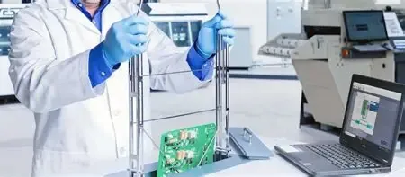
The PCB cleaning process typically follows soldering and involves aqueous, semi-aqueous, or solvent-based methods selected according to flux type and board complexity. Inline spray systems, ultrasonic tanks, and vapor degreasers remove residues while minimizing damage to sensitive components. Process parameters such as temperature, dwell time, and rinse quality are controlled to achieve target cleanliness levels. Industry standards provide the framework for acceptable residue limits and test methods. Reference to IPC J-STD-001 appears once in process qualification discussions, while IPC-A-610 guides visual and cleanliness acceptance criteria during final inspection. These standards ensure that cleaning effectiveness is verified rather than assumed.
Best Practices for Maintaining PCB Assembly Cleanliness
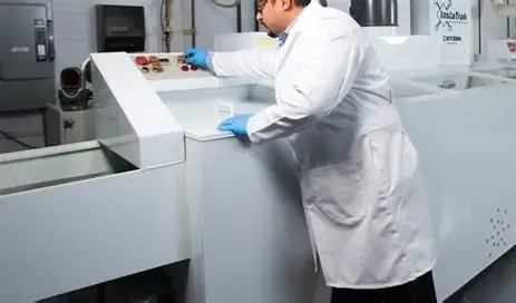
Factories implement controlled environments with appropriate cleanroom classifications for critical assembly stages. Automated optical inspection after cleaning confirms residue removal before protective coatings are applied. Process audits track ionic contamination levels at regular intervals using extraction methods specified in relevant standards. Design considerations, such as adequate spacing between high-voltage traces and selection of low-residue fluxes, reduce the cleaning burden. Operator training emphasizes proper handling techniques and immediate cleaning of any visible spills. Validation of the entire cleaning process through repeated testing confirms that target cleanliness metrics are consistently achieved across production batches.
Conclusion
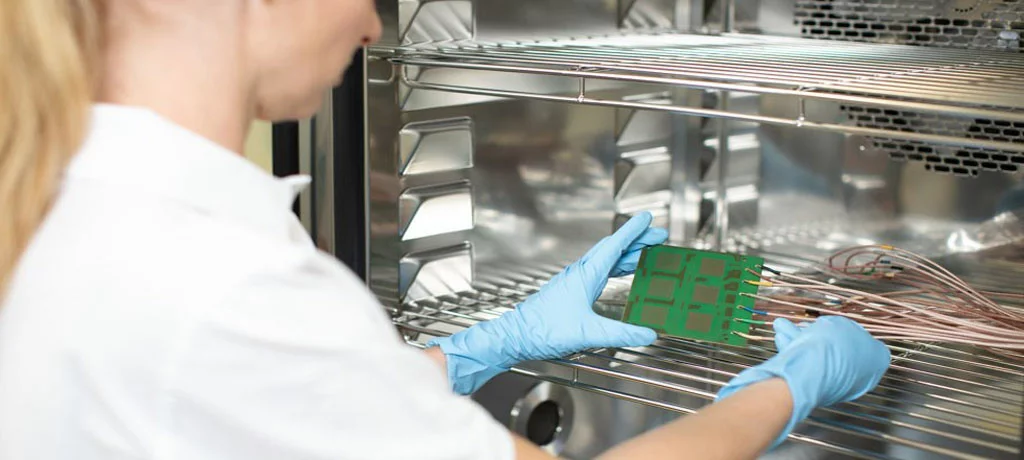
Cleanliness in electric vehicle PCB manufacturing is essential for preventing corrosion, maintaining electrical integrity, and ensuring long-term reliability under automotive operating conditions. Systematic application of the PCB cleaning process, guided by established standards, removes contaminants that would otherwise compromise performance. Factory practices that integrate cleaning verification into every stage of production deliver assemblies capable of withstanding the thermal, mechanical, and environmental stresses unique to EVs. Attention to PCB assembly cleanliness ultimately supports safer and more dependable vehicle electronics.
FAQs
Q1: What role does the PCB cleaning process play in preventing PCB contamination during EV manufacturing?
A1: The PCB cleaning process removes flux residues, ionic compounds, and particulates that remain after soldering and handling. By reducing surface contamination levels, it prevents the formation of conductive paths and electrochemical migration that can occur in humid or high-voltage environments typical of electric vehicles. Consistent cleaning supports long-term insulation resistance and reduces the likelihood of corrosion-related failures in battery management and power control modules.
Q2: How do PCB cleaning standards help manufacturers control PCB assembly cleanliness?
A2: PCB cleaning standards define acceptable residue limits, test methods, and acceptance criteria for assemblies. They provide objective benchmarks that factories use to qualify cleaning equipment, validate processes, and perform routine audits. Compliance with these standards ensures that cleanliness levels remain within ranges that protect against corrosion and electrical leakage throughout the vehicle service life.
Q3: Why is preventing PCB corrosion especially important for electric vehicle applications?
A3: Electric vehicle PCBs experience continuous exposure to temperature extremes, vibration, moisture, and road chemicals. Corrosion initiated by residual contaminants can degrade high-voltage connections and safety systems over time. Effective prevention through thorough cleaning maintains conductor integrity and insulation performance, reducing the risk of field failures that affect vehicle operation and occupant safety.
Q4: What practical steps improve PCB assembly cleanliness in high-volume production?
A4: Manufacturers adopt controlled handling procedures, select low-residue materials where feasible, and integrate automated cleaning followed by verification testing. Regular monitoring of ionic contamination and process parameter adjustments maintain consistent results. These steps, aligned with recognized standards, help sustain cleanliness across large production runs without introducing bottlenecks.
References
IPC J-STD-001: Requirements for Soldered Electrical and Electronic Assemblies
IPC-A-610: Acceptability of Electronic Assemblies





