 ALLPCB


Introduction
Industrial automation equipment relies on reliable electrical interconnections to maintain continuous operation in demanding settings. PCB connectors serve as the critical interface between printed circuit boards and external wiring, sensors, actuators, and power sources. Selecting appropriate connectors directly influences system uptime, safety, and long-term performance. Engineers must evaluate electrical, mechanical, and environmental factors to match connector specifications with application requirements. Proper selection prevents failures that could lead to costly downtime or equipment damage.
Why Connector Selection Matters for Industrial Applications
In industrial environments, connectors face exposure to vibration, temperature extremes, dust, moisture, and electromagnetic interference. Incorrect choices can result in intermittent connections, corrosion, or complete failure under load. Industrial PCB connector types vary widely in form factor, termination style, and sealing capabilities. High-reliability PCB connectors incorporate features such as locking mechanisms and robust materials to withstand these stresses. Procurement teams and designers benefit from understanding these variables early in the project to avoid redesigns. Selecting connectors for harsh environments requires balancing performance needs with cost and availability constraints.
Overview of Common Industrial PCB Connector Types
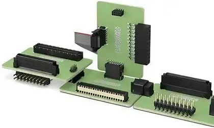
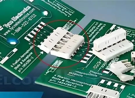
Board-to-board connectors enable direct stacking or parallel mounting of PCBs within control cabinets. Wire-to-board connectors facilitate connections from external cables to the board, often using crimp or insulation displacement technology. Circular connectors provide robust mating in panel-mounted applications and support higher pin counts. Rectangular connectors with modular inserts allow customization for power, signal, and data transmission in a single housing. Each type offers distinct advantages in density, ease of assembly, and maintenance access. Engineers evaluate mating cycles, polarization features, and contact materials when matching types to specific automation tasks.
Environmental Considerations in Harsh Settings
Temperature cycling causes expansion and contraction that stresses connector interfaces and solder joints. Vibration from motors or conveyors can loosen contacts unless connectors include secure latching or screw-locking designs. Dust and particulate ingress degrade insulation resistance over time. Moisture leads to corrosion of contacts and reduced dielectric strength. Selecting connectors for harsh environments involves reviewing ingress protection ratings and material compatibility with cleaning agents or chemicals present on the factory floor. Testing protocols outlined in relevant standards help verify performance under simulated conditions.
Electrical Ratings: Current, Voltage, and Power Handling
Connector current and voltage ratings must exceed the maximum expected loads with appropriate derating for temperature and altitude. Contact resistance affects heat generation and voltage drop, particularly in high-current power distribution paths. Insulation materials determine the maximum voltage the connector can safely handle without breakdown. Engineers calculate continuous and peak current requirements while considering derating curves provided by manufacturers. Over-specifying ratings adds unnecessary cost and size, while under-specifying risks overheating or arcing. Proper rating selection ensures compliance with system safety margins.
Mechanical Reliability and Mating Durability
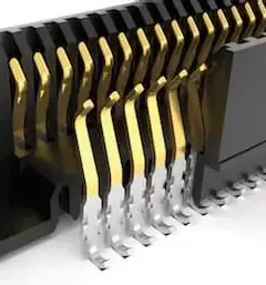
Contact retention force and durability under repeated mating cycles determine long-term reliability. Gold or silver plating on contacts reduces oxidation and maintains low resistance in industrial atmospheres. Housing materials such as high-temperature thermoplastics resist deformation during soldering or operation. Polarization and keying prevent incorrect mating that could damage pins or cause short circuits. Vibration resistance often requires secondary locking features or potting compounds around the connector body. These mechanical attributes directly impact maintenance intervals and overall equipment effectiveness.
Waterproof and Sealed Connectors for Industrial Use
Waterproof PCB connectors for industrial use incorporate gaskets, O-rings, or overmolded seals to achieve high ingress protection levels. Ratings such as IP67 or IP68 indicate resistance to dust and temporary or continuous water immersion. Sealing must remain effective after repeated mating cycles and exposure to temperature extremes. Cable entry points require strain relief and proper sealing to prevent water wicking along conductors. Selection involves matching the IP rating to the specific environmental hazards identified in the application risk assessment. Proper installation techniques, including correct torque on locking nuts, preserve the intended protection level.
Best Practices for Selection and Integration
Begin by compiling a detailed requirements matrix covering electrical loads, environmental exposure, mating frequency, and space constraints. Cross-reference candidate connectors against applicable industry standards for performance verification. Consider assembly processes such as wave soldering, reflow, or press-fit termination and their impact on connector integrity. Plan for testing of mated pairs under expected vibration and thermal profiles before finalizing the design. Document selection rationale to support future maintenance or upgrades. Collaboration between design, manufacturing, and procurement teams reduces the likelihood of compatibility issues during production.
Conclusion
Choosing suitable PCB connectors requires systematic evaluation of electrical ratings, mechanical features, and environmental protection. Attention to industrial PCB connector types and their suitability for harsh environments supports reliable automation system performance. Adherence to established standards such as IEC 60529 for ingress protection and IPC-A-610 for assembly acceptability provides a consistent framework for verification. Thorough documentation and testing during the selection process minimize risks and extend equipment service life. Engineers who apply these principles achieve robust interconnections that meet the demands of modern industrial automation.
FAQs
Q1: What are the primary industrial PCB connector types used in automation equipment?
A1: Common types include board-to-board, wire-to-board, circular, and rectangular connectors. Each supports different pin densities, current capacities, and mounting styles suited to control panels, sensors, and actuators. Selection depends on space, mating requirements, and environmental exposure.
Q2: How do engineers evaluate connectors for harsh environments?
A2: Engineers assess temperature range, vibration resistance, dust and moisture ingress, and chemical compatibility. They review ingress protection ratings and material specifications to ensure long-term reliability under factory floor conditions.
Q3: Why are connector current and voltage ratings important?
A3: Ratings determine the safe operating limits for power and signal transmission. Proper selection with derating prevents overheating, voltage drop, and insulation failure in continuous industrial duty cycles.
Q4: What role do waterproof PCB connectors play in industrial applications?
A4: Waterproof connectors protect against dust and liquid ingress in washdown or outdoor automation setups. They maintain electrical integrity and prevent corrosion when equipment requires regular cleaning or operates in humid conditions.
References
IEC 60529 — Degrees of protection provided by enclosures (IP Code). IEC.
IPC-A-610G — Acceptability of Electronic Assemblies. IPC.
J-STD-001G — Requirements for Soldered Electrical and Electronic Assemblies. IPC.


