 ALLPCB


Why Marine PCB Durability Matters
Electronic failures at sea can compromise vessel safety and operational continuity. Saltwater acts as an electrolyte that promotes electrochemical corrosion on exposed copper traces and component leads. Vibration induces mechanical fatigue in solder joints and traces, while thermal cycling causes expansion mismatches that lead to cracking. Procurement teams and designers therefore prioritize durability specifications early in projects. Compliance with established industry practices helps meet performance expectations in applications such as sonar, radar, and engine monitoring.
Corrosion Mechanisms in Saltwater Environments
Saltwater accelerates corrosion through ionic conduction and galvanic action between dissimilar metals. Chloride ions penetrate protective layers and initiate pitting on copper surfaces. Over time, this process increases resistance, creates open circuits, and degrades signal integrity. Temperature fluctuations further exacerbate moisture ingress and condensation within enclosures. Understanding these mechanisms guides the selection of appropriate PCB materials for saltwater conditions and protective measures that interrupt the corrosion pathway.
Vibration and Mechanical Stress Factors
Marine vessels transmit continuous low-frequency vibration and occasional shock loads to mounted electronics. These forces cause cyclic bending in the PCB substrate and fatigue in interconnects. Solder joints are particularly vulnerable where component mass creates stress concentrations. Thermal expansion differences between the board and components compound mechanical strain during temperature changes. Structured analysis of these combined loads informs layout decisions that distribute stress more evenly.
Thermal Management Challenges at Sea
Enclosed marine electronics often operate in high-ambient temperatures with limited airflow. Power dissipation from processors and power components raises local temperatures, accelerating material aging and reducing reliability. Heat buildup also promotes moisture migration and coating degradation. Effective thermal management marine PCBs therefore requires consideration of both steady-state heat flow and transient spikes from load changes. Proper via placement, copper balancing, and material thermal conductivity play central roles in maintaining acceptable operating temperatures.
Practical Design Guidelines for Durability
Designers begin by specifying substrates with elevated glass transition temperatures and low moisture absorption to resist dimensional changes. Thicker copper foils and enhanced surface finishes improve current-carrying capacity and corrosion resistance. Component placement avoids high-stress zones near mounting points, while trace routing minimizes sharp corners that concentrate vibration energy. Ground planes and stiffening features increase overall rigidity without excessive weight. These choices align with logical engineering evaluation of expected environmental loads.
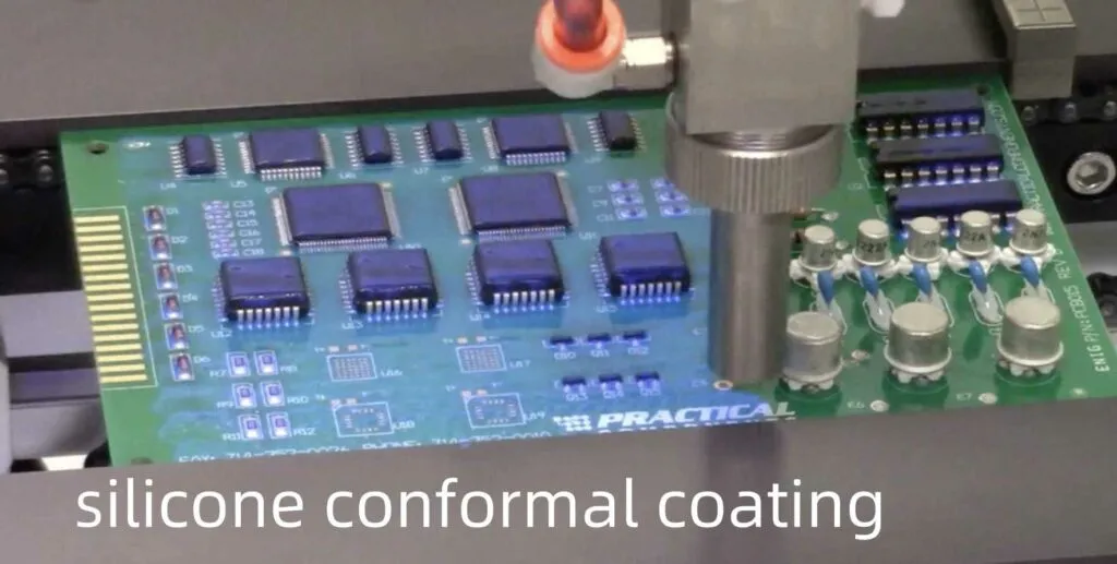
Protective Coatings and Encapsulation
Conformal coating marine PCBs provides a barrier against moisture, salt, and contaminants. Silicone and polyurethane formulations offer flexibility and adhesion suitable for vibration-prone assemblies. Application thickness and coverage uniformity directly affect protection levels. Selective coating around connectors and test points maintains accessibility while shielding critical areas. Post-coating inspection verifies absence of voids or bubbles that could trap moisture.
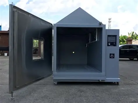
Testing and Validation Approaches
Validation combines environmental simulations with functional checks. Thermal cycling, humidity exposure, and vibration testing according to recognized protocols reveal weaknesses before field deployment. Salt fog testing evaluates corrosion resistance of coatings and finishes. Mechanical shock and random vibration profiles replicate shipboard conditions. Results guide iterative refinements to layout, materials, and assembly processes.
Assembly and Quality Considerations
Assembly processes must preserve design intent through controlled soldering profiles and handling procedures. Moisture-sensitive components require proper baking and storage to prevent defects during reflow. Inspection criteria emphasize joint integrity and coating adhesion. Documentation of process parameters supports traceability and continuous improvement. These steps ensure that theoretical durability translates into manufactured hardware.
Conclusion
Marine PCB durability results from integrated attention to corrosion, vibration, thermal, and moisture factors throughout design and production. Adherence to established standards such as those from IPC provides a consistent framework for specification and acceptance. Systematic application of these principles yields electronics that maintain performance under demanding sea conditions.
FAQs
Q1: What are the primary marine PCB design guidelines for vibration resistance?
A1: Vibration-resistant PCB design begins with substrate selection and component layout that minimize stress concentrations. Engineers incorporate stiffeners, strategic mounting holes, and balanced copper distribution to reduce flexing. Solder joint geometry and underfill materials further enhance fatigue life. These measures collectively address cyclic loading typical of marine applications.
Q2: Which PCB materials perform best in saltwater environments?
A2: PCB materials for saltwater prioritize low moisture absorption and high chemical resistance. Laminates with elevated glass transition temperatures maintain dimensional stability when exposed to humidity and salt. Enhanced copper plating and compatible surface finishes slow corrosion progression. Material choices are validated through accelerated environmental testing.
Q3: How does conformal coating protect marine PCBs?
A3: Conformal coating marine PCBs creates a dielectric barrier that prevents direct contact between conductive surfaces and corrosive electrolytes. Flexible coatings accommodate board flexure without cracking. Proper application thickness and edge coverage determine long-term effectiveness. Regular inspection confirms coating integrity remains intact after environmental exposure.
Q4: What thermal management strategies suit marine electronics PCBs?
A4: Thermal management marine PCBs combines conductive paths such as thermal vias with material selections that conduct heat efficiently. Component spacing and copper pours distribute heat away from sensitive areas. Enclosure-level considerations, including heat sinking where feasible, complement board-level features. Validation through thermal imaging and cycling confirms performance under load.


