ALLPCB


Inductors play a fundamental role in many electronic circuits by storing energy in a magnetic field and opposing rapid changes in current. For electronic hobbyists, constructing a homemade inductor through diy inductor winding offers a practical way to obtain custom values that may not be readily available in standard component kits. This inductor construction tutorial focuses on the essential steps and considerations for creating functional coils at home. The process builds directly on basic electromagnetic principles and requires only modest tools and materials. Hobbyists often turn to homemade inductor designs when prototyping filters, oscillators, or power supply circuits where specific inductance values improve performance.
What Is an Inductor and Why It Matters
An inductor consists of a coil of wire, frequently wound around a core material, that generates inductance measured in henries. Inductance arises from the interaction between the electric current and the resulting magnetic field according to Faraday's law of electromagnetic induction. In hobbyist projects, homemade inductors appear in applications such as radio frequency tuning circuits, switch-mode power supplies, and audio crossovers. They help filter unwanted signals, smooth current flow, or store energy temporarily. Understanding inductor construction allows hobbyists to experiment with circuit behavior that off-the-shelf parts cannot always match precisely.
Technical Principles of Coil Winding
The inductance of a coil depends primarily on the number of turns, the cross-sectional area of the winding, the length of the coil, and the magnetic permeability of the core. Air-core designs provide low inductance with minimal losses at high frequencies, while ferromagnetic cores increase inductance but introduce frequency-dependent losses and potential saturation. Winding geometry affects the quality factor, or Q, through factors such as proximity effect and skin effect at higher frequencies. Even spacing between turns reduces parasitic capacitance that can limit high-frequency performance. Consistent tension during winding prevents loose turns that alter the effective inductance or create mechanical instability.
Industry standards such as those from IEC guide material selection and performance expectations for magnetic components in electronic assemblies. Proper insulation between wire layers prevents inter-turn shorts that would reduce effective turns and inductance. Hobbyists benefit from recognizing that core saturation occurs when the magnetic field strength exceeds the material limit, causing inductance to drop sharply under high current.
Practical Steps for DIY Inductor Winding
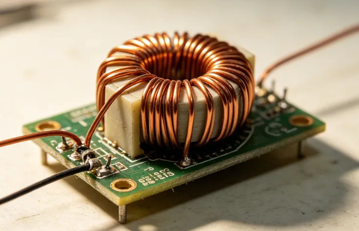
Begin by selecting magnet wire of appropriate gauge for the expected current and desired inductance. Thinner wire suits higher-frequency or lower-current applications, while thicker wire handles greater current without excessive heating. Choose a core such as a ferrite rod, powdered-iron toroid, or simple air form based on the target frequency range and space constraints. Secure the core or form and wind the wire in a single layer or multilayer configuration, maintaining even tension and uniform spacing.
Use a winding jig or hand-crank setup to achieve consistent turns. Count turns carefully, as each additional turn multiplies inductance roughly with the square of the total turns in air-core designs. After winding, secure the ends and apply insulating tape or varnish to protect the coil. Test the finished inductor by measuring its inductance with an LCR meter if available, or by observing its behavior in a simple resonant circuit.
Best Practices and Common Considerations
Maintain uniform winding density to minimize variations in inductance across production of multiple units. Avoid overlapping turns excessively in single-layer designs, as this increases parasitic capacitance. When using cores, select materials rated for the operating frequency to reduce core losses. Solder connections carefully to the wire ends after stripping insulation, ensuring low-resistance joints that do not introduce unwanted resistance.
Industry guidelines such as J-STD-001 outline acceptable practices for soldered connections in electronic assemblies, which apply when attaching leads to a homemade inductor. Store finished coils away from strong magnetic fields or mechanical stress that could alter their characteristics. For multilayer windings, insert insulating layers between sections to maintain electrical isolation. These steps improve reliability in hobbyist projects where repeated assembly and testing occur.
Troubleshooting Common Issues in Inductor Construction
Uneven winding often leads to inconsistent inductance or mechanical looseness that changes value over time. Shortened turns from insulation damage reduce effective inductance and may cause overheating under load. Core saturation manifests as distorted waveforms or reduced filtering effectiveness in power circuits. Measuring the coil before and after potting or mounting helps identify shifts introduced by mechanical handling.
Adjusting the number of turns or core material provides a direct way to correct measured values. Hobbyists frequently verify performance by substituting the homemade inductor into the target circuit and observing frequency response or current ripple. Consistent documentation of turns count, wire gauge, and core type supports repeatable results across projects.
Conclusion
DIY inductor winding empowers electronic hobbyists to create custom components tailored to specific circuit needs. Attention to winding uniformity, core selection, and insulation practices directly influences the final inductance and performance. Following established electromagnetic principles and relevant industry standards supports reliable outcomes without requiring specialized manufacturing equipment. Experimentation with different configurations builds practical understanding of how geometry and materials interact.
FAQs
Q1: How does diy inductor winding affect circuit performance compared to commercial parts?
A1: Diy inductor winding allows precise control over inductance value and physical size, which can optimize filter cutoff frequencies or energy storage in hobbyist designs. Consistent winding technique and core choice determine losses and parasitic effects that influence overall circuit efficiency and stability. Hobbyists often achieve comparable results to commercial inductors when following structured construction methods.
Q2: What core materials work best for a beginner homemade inductor?
A2: Air cores suit high-frequency applications with low inductance needs and minimal losses, while ferrite or powdered-iron cores increase inductance for lower-frequency power or audio uses. Selection depends on the target operating frequency and current levels to avoid saturation. Beginners typically start with readily available ferrite rods for straightforward winding experiments.
Q3: How can I verify the inductance of a coil made through inductor construction tutorial methods?
A3: An LCR meter provides direct measurement of the finished coil. Alternatively, placing the homemade inductor in a resonant circuit with a known capacitor and observing the oscillation frequency allows indirect calculation of inductance. Multiple measurements confirm consistency before final circuit integration.
Q4: What common errors occur during diy inductor winding and how are they avoided?
A4: Uneven tension or overlapping turns introduce parasitic capacitance and variable inductance. Using a winding form with guides and applying steady tension throughout the process prevents these issues. Checking insulation integrity before and after winding reduces the risk of shorted turns that degrade performance.
References
J-STD-001G — Requirements for Soldered Electrical and Electronic Assemblies. IPC, 2017
IEC 62368-1 — Audio/Video, Information and Communication Technology Equipment. IEC, 2018